Tb1 tb2, 6 ul power-limited wiring requirements, Nc c c no no – Fire-Lite CMP-2402B Fire Alarm Control Panel User Manual
Page 23: Relay terminals, 23 ul power-limited wiring requirements, Gnd ac tbl buz alarm trouble, Figure 2-9
Document #50907 Rev. A1 12/03/02 P/N 50907:A1
23
UL Power-limited Wiring Requirements
Standard Relays
The FACP provides two Form-C relays rated for 2.0 amps @ 30 VDC (resistive) and 2.0 amps @ 30 VAC
(resistive).
2.6
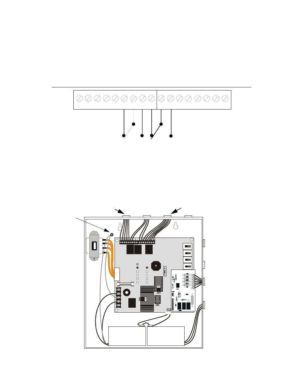
UL Power-limited Wiring Requirements
Power-limited and nonpower-limited circuit wiring must remain separated in the cabinet. All power-limited circuit
wiring must remain at least 0.25" (6.35 mm) away from any nonpower-limited circuit wiring. Furthermore, all
power-limited and nonpower-limited circuit wiring must enter and exit the cabinet through different knockouts and/or
conduits. A typical wiring diagram for the FACP is illustrated below.
TB1
TB2
GND AC TBL BUZ
ALARM
TROUBLE
+
+
+
+
-
-
-
NC
NC
C
C
NO
NO
SIGNAL
OUTPUT
INITIATING
ZONE 1
INITIATING
ZONE 2
FIGURE 2-8:
Relay Terminals
Relay connections may be power-limited or nonpower-limited, provided that a minimum of 0.25"
is maintained between conductors of power-limited and nonpower-limited circuits.
M240
1REL
.CDR
J3
J1
F2
J4
J5
TB3
TB1
GND
+24V
REG
RES
BUZ
TROUBLE
NE
U
T
RA
L
E
A
R
T
H
HO
T
SIGNAL
OUTPUT
CUT IF 4X
OPTION
BOARD IS
PRESENT
CUT TO
DISABLE
EARTH
FAULT
INITIAT
ZONE 1
INITIAT
ZONE 2
ALARM
TB
L S
ILE
N
C
E
SI
G SI
L
E
N
C
E
ZO
NE
1
SI
G SI
L
E
N
C
E
ZO
NE
2
SY
S
TEM
R
E
SET
NC
NC
C
C
-
-
-
+
+
+
NO
NO
TBL
AC
TB2
R72
R14
SW4
SW2
SW1
SW3
CA
U
T
IO
N
!
HIG
H
VO
LT
A
G
E
BATTERY
FIGURE 2-9:
Typical Wiring Diagram for UL Power-limited Requirements
Power-limited
Circuit
Power-limited
Circuit
Nonpower-limited
Circuit
Power-limited
Circuit
AC Power
Grounding Stud
24
01P
WRL.C
D
R