Installation, 1 mounting options, 2 backbox mounting – Fire-Lite CMP-2402B Fire Alarm Control Panel User Manual
Page 17: Chapter 2
Document #50907 Rev. A1 12/03/02 P/N 50907:A1
17
Installation
CHAPTER 2
Installation
2.1
Mounting Options
The cabinet may be either semi-flush or surface mounted.
The door is removable during the installation period by open-
ing and lifting the door off the hinges. The cabinet mounts
using two key slots and two additional 0.250” (0.635 cm)
diameter holes located in the backbox. The key slots are
located at the top of the backbox and the two securing holes
at the bottom.
Carefully unpack the system and check for shipping damage.
Mount the cabinet in a clean, dry, vibration-free area where
extreme temperatures are not encountered. The area should
be readily accessible with sufficient room to easily install and
maintain the panel. Locate the top of the cabinet approxi-
mately five feet above the floor with the hinge mounting on
the left. Determine the number of conductors required for the
devices to be installed. Sufficient knockouts are provided for
wiring convenience. Select the appropriate knockout(s) and
pull the required conductors into the box. Note that there are
no knockouts on the left (hinged) side of the cabinet. All
wiring should be in accordance with the National and/or
Local codes for fire alarm systems.
2.2
Backbox Mounting
1.
Open the door.
2.
Remove the main PC board assembly by unscrewing the four screws in the corners of the board. Set the board
aside in a safe, clean place. Avoid static discharge which may damage the board.
3.
Mark and predrill holes for the top two keyhole mounting bolts using the dimensions illustrated in Figure 2-2.
4.
Install two upper fasteners in the wall with the screw heads protruding.
5.
Using the upper keyholes, mount the backbox over the two screws.
6.
Mark and drill the lower two holes.
7.
Mount the backbox, install the remaining fasteners and tighten.
8.
When the location is dry and free of construction dust, reinstall the main PC board.
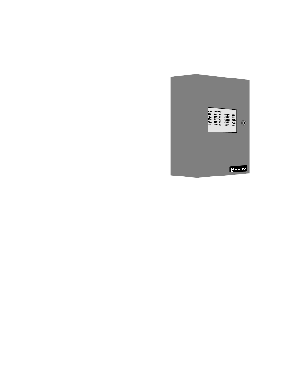
FIGURE 2-1:
CMP-2401B/CMP-2402B Mounting
MP
2
401DR.
CDR