4 circuits, 5 components – Fire-Lite CMP-2402B Fire Alarm Control Panel User Manual
Page 15
Document #50907 Rev. A1 12/03/02 P/N 50907:A1
15
Circuits
1.4
Circuits
Input Circuits
The CMP-2401B has one IDC (Initiating Device Circuit) and the CMP-2402B has two IDCs. Input circuit(s) pro-
vide Style B (Class B) configuration and accept 2-wire smoke detectors and normally-open contact devices.
Output Circuits
• 24 Volt Resettable Power Output 85 mA
• 24 Volt Battery Charger (up to two 7 AH batteries)
Notification Appliance Circuit
One Style Y (Class B) Notification Appliance Circuit @ 1.25 amps maximum
Relays
Two dry Form-C relays for system alarm and system trouble are provided standard. Contacts are rated 2.0 amps
@ 30 VDC (resistive), 2.0 amps @ 30 VAC (resistive).
Battery Charger
The battery charger will charge up to two 7 AH batteries. The FACP cabinet holds a maximum of two 7 AH
batteries.
1.5
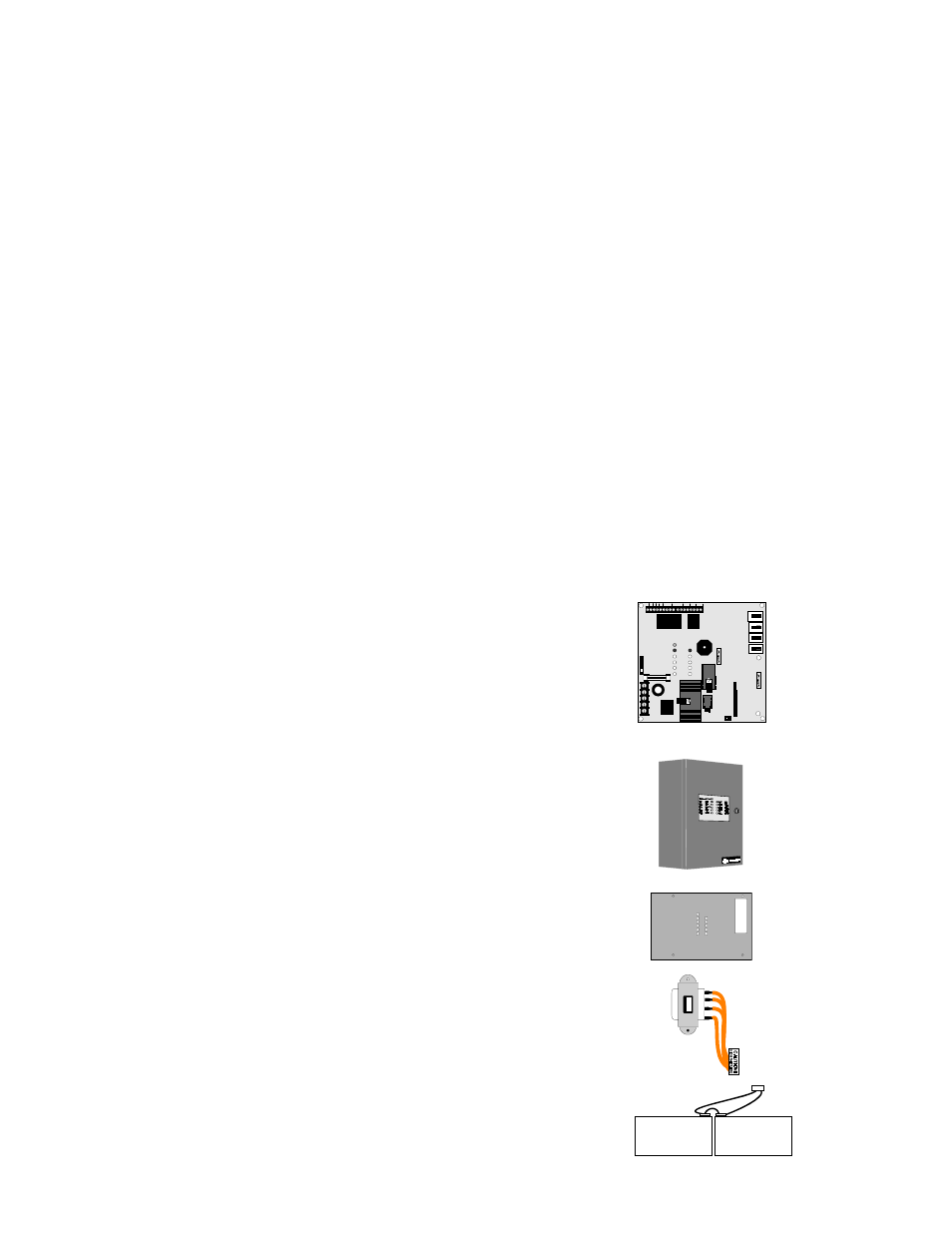
Components
Main Circuit Board
The main circuit board contains power supply, alarm and trouble
relays, control switches, LED indicators, option jumpers, wiring
interface connectors and other primary components. The option
module plugs in and is mounted to the main circuit board. The
main circuit board is delivered premounted in the cabinet.
Cabinet
The cabinet is red. The backbox measures 14.5" (36.83 cm)
high X 12.5" (31.75 cm) wide X 2.875" (7.303 cm) deep and
provides space for two batteries (up to 7.0 Amp Hours each).
Also supplied is a blue dress panel which mounts inside the
cabinet.
Dress Panel
A blue dress panel, which is required for Canadian
installations, is provided with the cabinet. The dress panel
restricts access to the system wiring while allowing access to
the control switches.
Transformer Assembly
One transformer is provided standard with the panel. The
transformer plugs into connector J5 on the main circuit board.
Batteries
The cabinet provides space for two 7 Amp Hour batteries
which must be ordered separately.
J1
F2
J4
J5
TB3
TB1
GND
+24V
REG
RES
BUZ
TROUBLE
NE
U
T
RAL
EA
R
T
H
H
O
T
SIGNAL
OUTPUT
CUT IF 4X
OPTION
BOARD IS
PRESENT
CUT TO
DISABLE
EARTH
FAULT
INITIAT
ZONE 1
INITIAT
ZONE 2
ALARM
J3
BATTERY
T
B
L S
ILE
N
C
E
SI
G
SI
LE
N
C
E
ZO
N
E
1
SI
G
SI
LE
N
C
E
ZO
N
E
2
S
YST
E
M
R
E
S
E
T
NC
NC
C
C
-
-
-
+
+
+
NO
NO
TBL
AC
TB2
R72
R14
SW4
SW2
SW1
SW3
2402
BO
RD
.CDR
MP
240
1DR.CDR
DP-
240
1.CDR
2401
XF
O
R
.CDR
2401
BA
T
T
.CDR