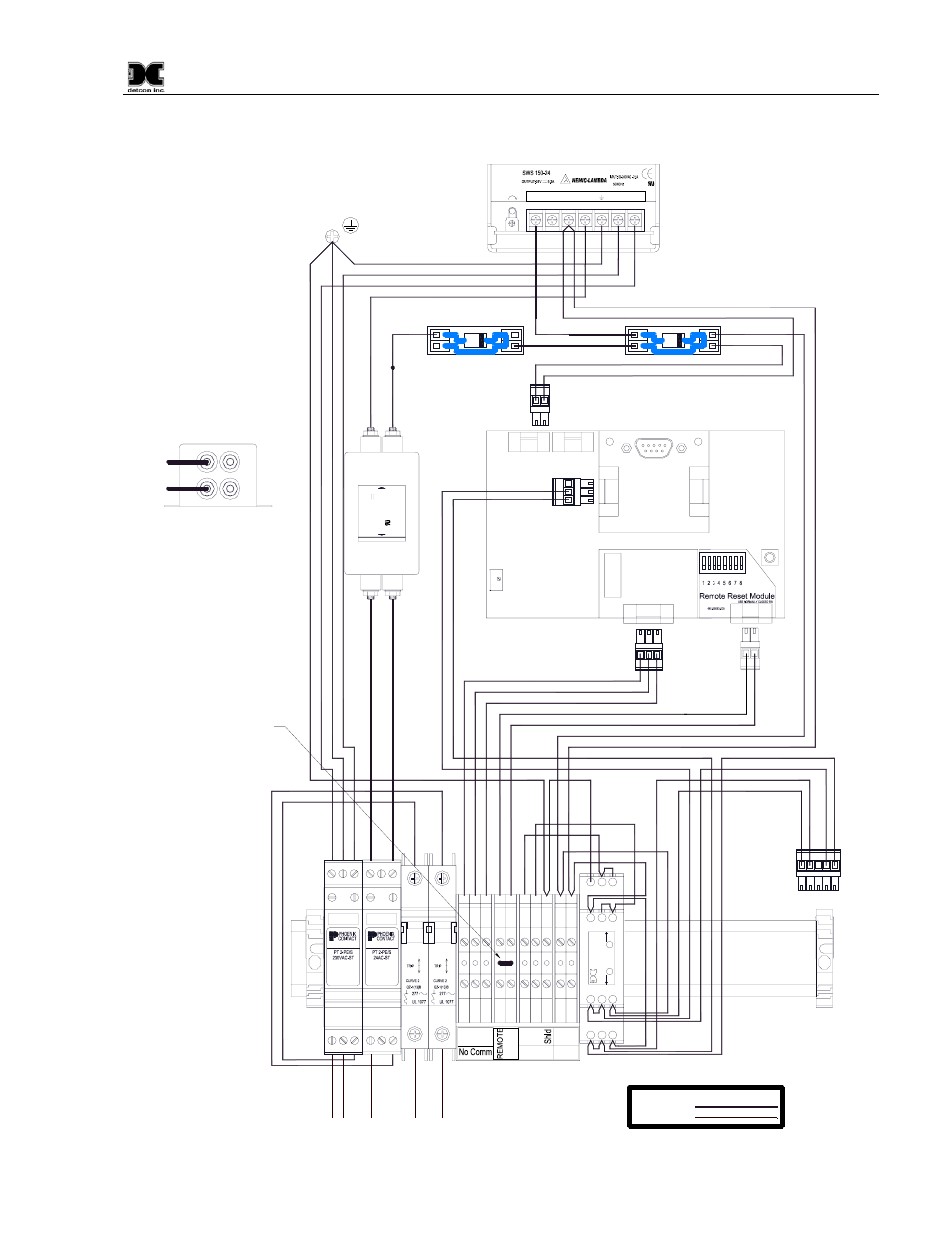
Figure 42 interconnect wiring – Detcon 6400-N1P User Manual
Page 41
1600/6400-N1P
1600/6400-N1P- Instruction Manual
Rev. 1.1
Page 37 of 38
TB1
PLUGTRUB
PLUGTRUB
7
6
5
12
11
10
14
13
N
Gnd
L1
1
2
3
4
5
6
1
2
3
4
5
6
3
4
S B A
-
+
Whi
te
18A
WG
G
ree
n 18
A
W
G
Bl
ack 18A
WG
Red 16AWG
Red 18AWG
Red 16AWG
Red 16AWG
Red 18AWG
Purple 18AWG
Black 16AWG
Red 16AWG
O
ran
ge
1
8
A
W
G
Bl
lue 18
AW
G
Y
e
llo
w 1
8
A
W
G
Purple 18AWG
White 18AWG
Black 18AWG
Red 18AWG
Green 18AWG
Black 18AWG
White 18AWG
Bl
ack 18
AW
G
R
ed 18AW
G
2
1
N
eutr
al
(
L2)
Gr
oun
d
VAC
(
L
1)
+VDC
- V
D
C
Customer Supplied Power
Customer Connections
Legend:
Pre-Wired
Customer Wired
Re
d 16
AW
G
+V
-V
L
N
+V
-V
V ADJ
H
MADE IN CHINA
Black 16AWG
Red 16AWG
D1
D2
GROUND
O
I
5A
O
I
2A
C
NO
NC
A
B
+
-
RS-485 VDC
Customer
9
8
R
ESET
L
I
N
E
L
0
A
D
15
D
C
F
6
F7905
1
5 A
M
P
80
V
co
rc
o
m
G
ra
y
18A
WG
G
ra
y
18A
WG
Bl
ack 16A
WG
-VDC RTN
-VDC RTN
Connections shown
for clarity only.
Connections shown
for clarity only.
Black 16AWG
Black 18AWG
Gray 18AWG
Gray 18AWG
Orange 18AWG
Bllue 18AWG
Yellow 18AWG
Note1:
Wiring shown for clarity only.
Correct connections shown
above.
RTN connected to +24VDC.
-VDC connected to -24VDC.
( For more information contact
Enrique Marrero)
-VDC
RTN
-VDC
RTN
-VDC
+VDC
Supplied
Modules
White 18AWG
Black 18AWG
Gr
ee
n 18A
WG
Bl
ack 18A
WG
Re
d 18
AW
G
Pur
p
le
18
AW
G
Whi
te
18AW
G
Re
d 18
AW
G
C B A
D
E
F
G H J
M
L
K
Da
ta
Da
ta
ww
w.de
tcon
.com
De
tc
on
Bl
ack 18A
WG
Pur
p
le
18
AW
G
Whi
te
18AW
G
Note1
W
hi
te 18AW
G
Pu
rp
le
18
AW
G
6400 Controller PCB
Serial Communications PCB
No Comm
VDC IN
RS-485
Primary
C
NO
NC
Fault Relay PCB
S
B
A
+
-
A
B
S
Secondary
RV1
J4
J3
J7
J3
J1
S2
J2
S1
RS-232
Note 2:
Jumper must be removed
if a Remote Alarm Reset
Switch is installed.
Figure 42 Interconnect Wiring