0 start-up, 1 applying power, 2 setting device identification on the i/o modules – Detcon 6400-N1P User Manual
Page 13: Start, Applying power, Setting device identification on the i/o modules, Figure 12 power in, 0 start
1600/6400-N1P
1600/6400-N1P- Instruction Manual
Rev. 1.1
Page 9 of 38
4.0 Start
-
Up
4.1 Applying
Power
Before applying power, make sure that all I/O Modules are correctly installed and that all wiring connections
between I/O modules and external devices are made correctly.
NOTE: Applying power with devices hooked up incorrectly may cause damage.
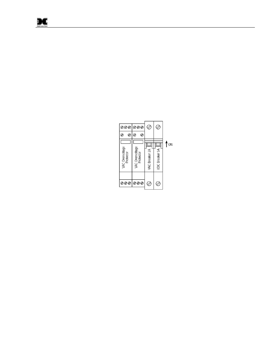
Turn the applicable AC Breaker and DC Breaker switches to the ON positions. Verify that the main touch-
screen LCD comes up displaying gas readings on the display. After 5 seconds, verify that all the I/O modules
are being polled by observing a sequence of blinking LED’s on the I/O Modules representing successful serial
communication. Enter and exit the “Program Menu” to bring the Main Display quickly up to date after power
boot-up.
Figure 12 Power In
NOTE: The polling of the input devices takes place more frequently than the communications to the relay
output devices. The sequence of polling communication will follow the order of the I/O device switch
addresses.
4.2 Setting Device Identification on the I/O Modules
NOTE: If your Model 1600/6400 controller has been configured at Detcon, you may elect to skip to the
Operator Interface (Section 5.0) for further review of system operation.
For a unit that has not been properly configured, the I/O modules must be serially addressed to establish
correct communications. Typically, the I/O modules will be identified from 01 to FF starting from the module
on the right hand side of the stack. The I/O module’s identification is established by setting the two rotary
switches to the correspondingly correct position. The top rotary switch sets the most significant bit (MSB).
The bottom rotary switch sets the least significant bit (LSB). For an address of 01, set the top switch to 0 and
the bottom switch to 1. See 14.2 Hexadecimal Table for Decimal to Hexadecimal conversion.
NOTE: All addresses must be unique. There can be no duplication of addresses or failure to
communicate will occur.
NOTE: Not all I/O modules communicate on every polling pass. Input modules are polled more often
than output modules.