0 operator interface, 1 using the touch-screen display, 2 main display – Detcon 6400-N1P User Manual
Page 14: Operator interface, Using the touch-screen display, Main display, Figure 13 setting device addresses
1600/6400-N1P
1600/6400-N1P- Instruction Manual
Rev. 1.1
Page 10 of 38
RELAY
COMM
M
S
D
L
S
D
4-20mA
INPUT
COMM
M
S
D
L
S
D
4-20mA
INPUT
COMM
M
S
D
L
S
D
4-20mA
INPUT
COMM
M
S
D
L
S
D
4-20mA
INPUT
COMM
M
S
D
L
S
D
RELAY
COMM
M
S
D
L
S
D
RELAY
COMM
M
S
D
L
S
D
RELAY
COMM
M
S
D
L
S
D
M
S
D
L
S
D
0
12
3
4
5
678
9A
B
C
D
EF
0
12
3
4
5
678
9A
B
C
D
EF
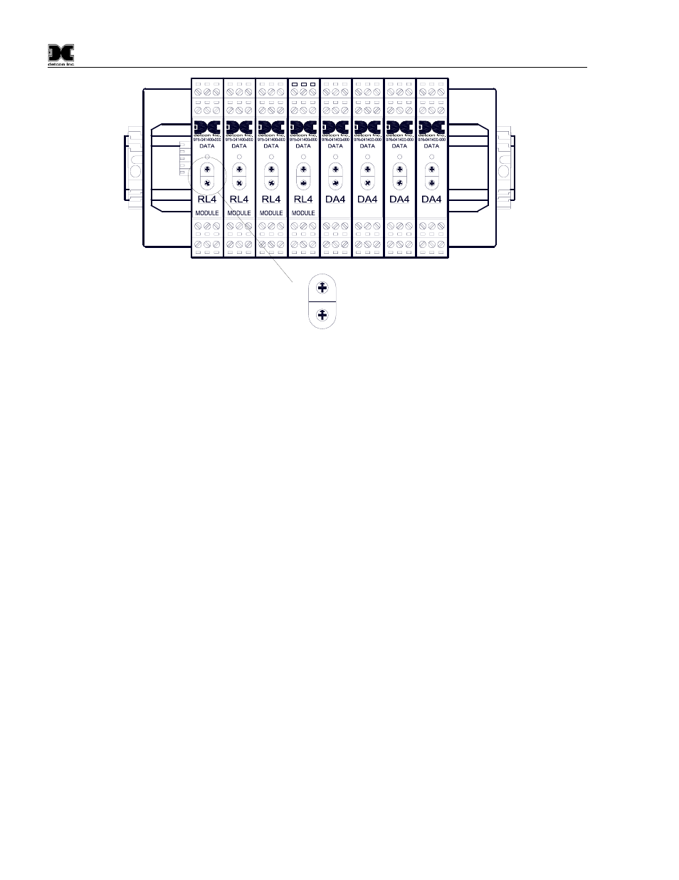
Figure 13 Setting Device Addresses
5.0 Operator
Interface
5.1 Using the Touch-screen Display
The Operator Interface is conducted through a graphic touch-screen backlit display. A suitable small blunt
device such as the Detcon stylus wand should be used to conduct touch-screen interaction.
NOTE: Sharp objects such as pens, pencils, screwdrivers…. etc. will permanently damage the display
and void the warranty. The use of fingertips to activate keys is permissible, but is difficult due to the
small press key areas in some cases. A pencil’s eraser tip is a suitable alternative.
In general, displayed items that are outlined with a box represent Press Keys. Press Keys should be firmly
pressed down for about 0.5 seconds to engage properly. They will illuminate momentarily when activated
properly.
The graphic display has backlighting that turns on after any touch-screen activity. It turns off automatically
after 1 minute of touch-screen inactivity. Backlighting will automatically be maintained during any abnormal
condition. The contrast and backlighting can be adjusted using the ‘Screen Utilities’ function described in
section 5.4.
5.2 Main
Display
The main display shows the status of the active gas channels. They are labeled by channel number, reading,
units and gas type. Example: CH1 - 0ppm - H2S. Under no-alarm condition, if the line entry is pressed it will
momentarily display the tag name for that channel. Example: CH1 Well Head #7.
When there is an active alarm or fault condition, the problem channel will be shown in reverse video. If this
line entry is then pressed, the current alarm/fault status will alternately be displayed. A channel number in
reverse video represents a channel that is actively in alarm/fault or has cleared alarm/fault but was set to
latching mode for the relay output.