3 select gas type and range, 4 set active alarm levels, Select gas type and range – Detcon 6400-N1P User Manual
Page 20: Set active alarm levels, Figure 21 select gas type, Figure 22 set alarm level, Menu (figure 21), The scalin, Figure 21) discussed in s, The scaling factor is used to ad
1600/6400-N1P
1600/6400-N1P- Instruction Manual
Rev. 1.1
Page 16 of 38
The second Model RL4 module set to 02 and handling sensor inputs 5 – 8, would appear as follows:
05
04
01
06
04
02
07
04
03
08
04
04
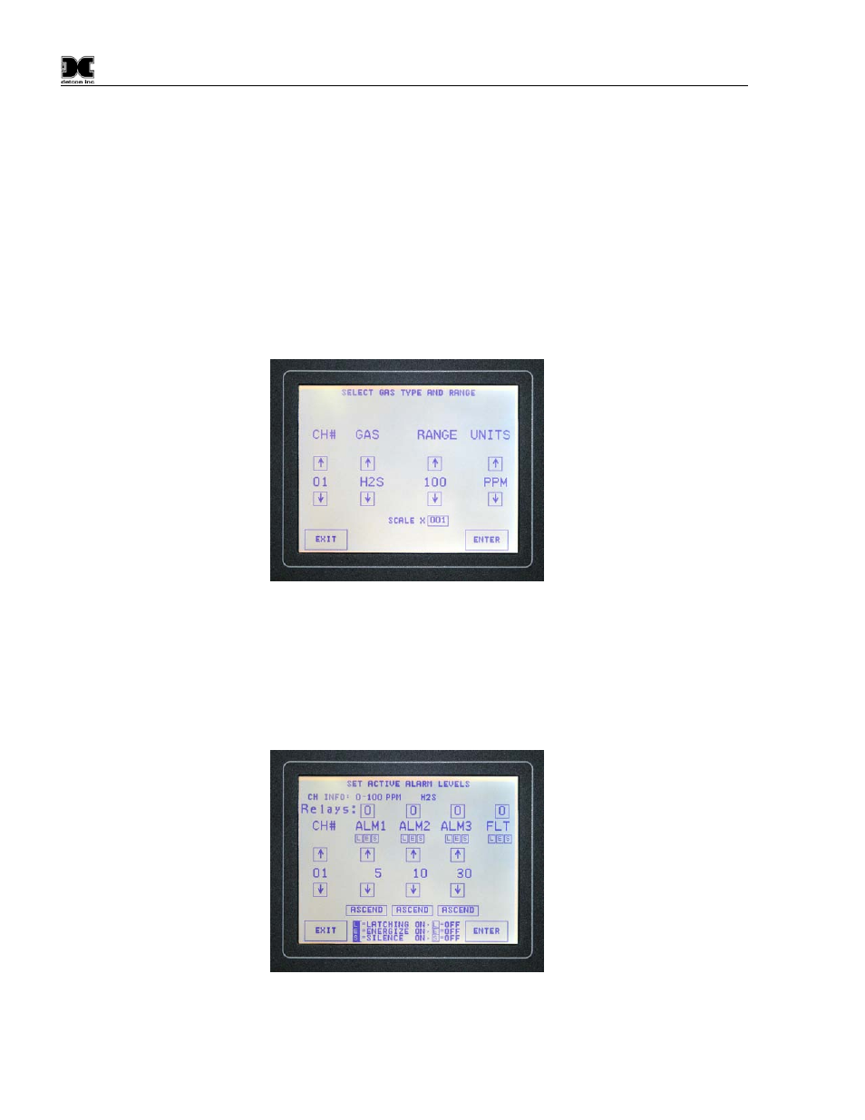
5.3.3 Select Gas Type and Range
Select Gas Type and Range is used to enter the sensor specific information for each gas channel. This
information includes Channel #, Gas type, full-scale range, and units. Rotate through each selection using the
up and down arrows for scrolling through the choice lists. When the correct selections for a given channel
have been made, press the ‘ENTER’ key. Press the ‘ENTER’ key after each channel’s selections are made.
The scale entry is only used, if applicable, for serial sensors and Mod 10 or 12 control cards.
Figure 21 Select Gas Type
5.3.4 Set Active Alarm Levels
The Set Active Alarm Level screen allows for the assignment of relay outputs to specific alarm or fault
conditions. At the top of the screen, the Channel Information is displayed for the current channel being set-up.
Example: CH INFO: 0-100ppm - H2S - Well Head #7. This information is provided as a reminder for which
gas sensor and tag number is being set up for alarm/fault.
Figure 22 Set Alarm Level
The line labeled “Relays” shows the Relay numbers to be assigned to each alarm or fault condition for the
selected channel. These are located directly above each of the three alarm conditions (ALM1, ALM2, ALM3)