Figure 19 addressing relay modules, Figure 20 addressing & set-up of relay outputs – Detcon 6400-N1P User Manual
Page 19
1600/6400-N1P
1600/6400-N1P- Instruction Manual
Rev. 1.1
Page 15 of 38
or 12 Control Card reading format is always in ### format. To properly display a 0-10ppm range, the X10
scaling factor must be used.
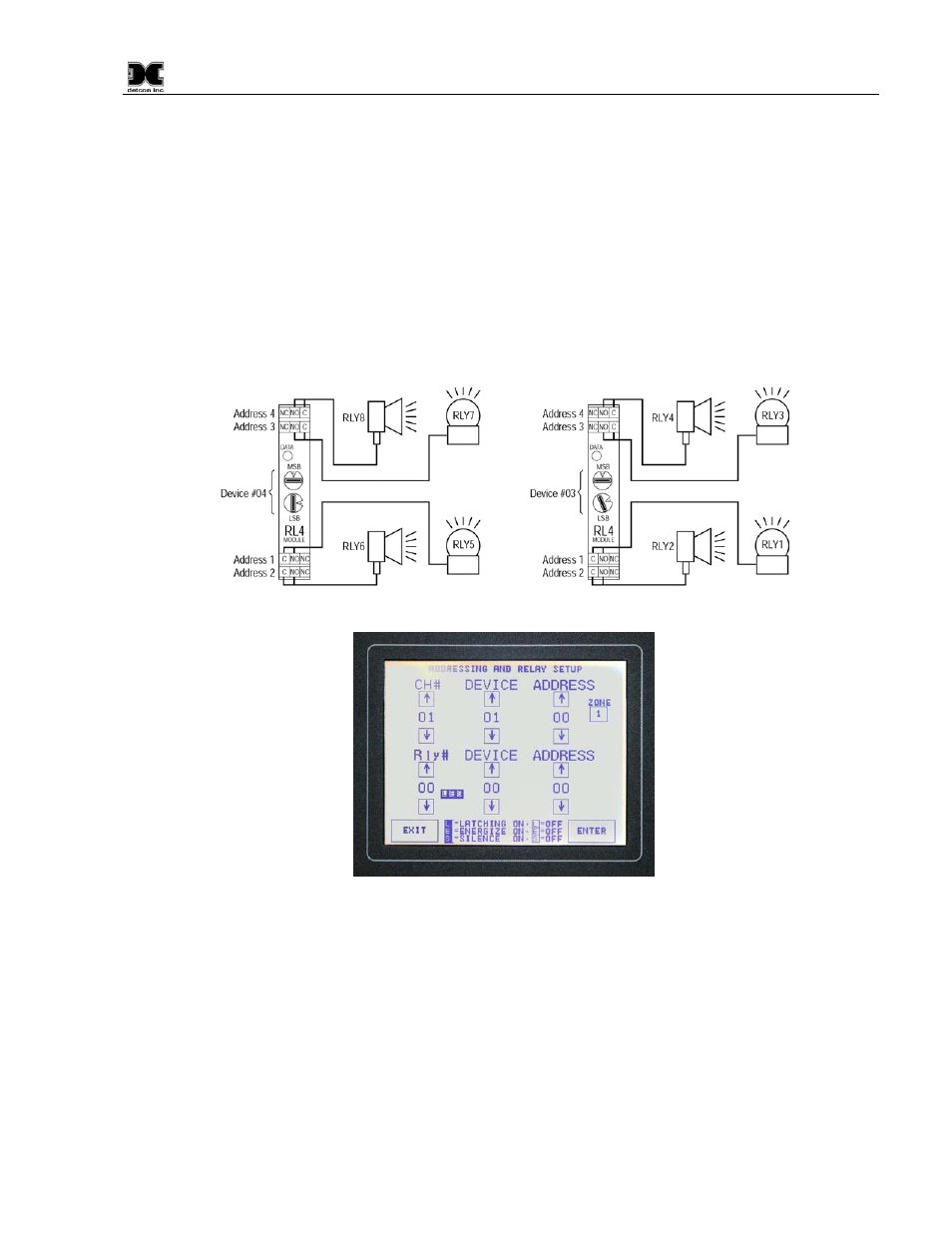
Addressing and Setup of Relay Outputs
For the Relay Output set-up, follow the same logic as with the gas channel set-up, except that there is no
relationship to ‘Zone’ assignment. In example, set the RL4 Relay Module # to 01 for the first relay output, set
the Device to 03 and the Address to 01. The second part of Relay Setup requires the decision of how the
individual relay contacts will be configured. Each relay must be selected as latching or non-latching,
energized or non-energized, and silenceable or non-silenceable. These selections are shown in three small
blocks to the right of the Relay # input. Make selections by pressing the LES blocks according to the
description key on the bottom middle of the screen (Figure 20).
Press the ‘ENTER’ key to save each relay entry as it is made. Continue this sequence for all other relays.
Figure 19 Addressing Relay Modules
Figure 20 Addressing & Set-up of Relay Outputs
NOTE: This selection controls the output state for that relay regardless of how many alarm/fault
conditions for which the relay output may be used. A single relay output can only be set up in one
configuration.
In a matrix table, the set-up for the first two Model RL4 modules would look like this:
Relay
#
Device
Address
01
03
01
02
03
02
03
03
03
04
03
04