4 base connector board, Base connector board, Figure 3 functional block diagram – Detcon 1000 User Manual
Page 7: Figure 4 dm-624 control circuit, Figure 5 connector board terminals
Mdl 1000 H2S E-Chem / Inst. Air
Model 1000 H2S E-Chem w Instrument Air
Rev. 1.1
Page 3 of 28
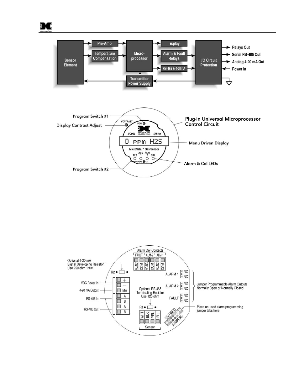
Figure 3 Functional Block Diagram
Figure 4 DM-624 Control Circuit
1.4 Base Connector Board
The base connector board is mounted in the explosion proof enclosure and includes: the mating connector for
the control circuit, reverse input and secondary transient suppression, input filter, alarm relays, lug less
terminals for all field wiring, and a terminal strip for storing unused programming jumper tabs. The alarm
relays are contact rated 5 amps @ 250VAC, 5 amps @ 30VDC and coil rated at 24VDC. Gold plated program
jumpers are used to select either the normally open or normally closed relay contacts.
Figure 5 Connector Board Terminals
See also other documents in the category Detcon Equipment:
- 12B (16 pages)
- FL-10 (7 pages)
- 10C Facilities (18 pages)
- 10C (29 pages)
- 10B (10 pages)
- 1212-N4X (9 pages)
- 812-N4X (9 pages)
- 1212B (5 pages)
- 612B (5 pages)
- 1610-N4X (28 pages)
- 1010-N4X (14 pages)
- 610-N4X (12 pages)
- 1610-N1 (4 pages)
- 810-N1-24VDC (10 pages)
- 410-N1-24VDC (4 pages)
- MCX-32-N1P (55 pages)
- RD-64X-N4X (41 pages)
- 880RA-N4X (36 pages)
- 880RA-N4X (23 pages)
- 880A-N1R (45 pages)
- 880A-N4X (50 pages)
- 880A-N4X (43 pages)
- X40-08-N4X (70 pages)
- 240 (33 pages)
- SW-AV1-N4 (12 pages)
- SW-AV2-DV1 (12 pages)
- A1V1 (9 pages)
- RXT-300 (47 pages)
- RXT-320 (31 pages)
- CXT-N4X (28 pages)
- SW-HMI-32-N4X (24 pages)
- SW-V1-DV2 (11 pages)
- SW-AV1-DV1 (14 pages)
- SW-AV2-DV2 (12 pages)
- SW-AV1-DV2 (12 pages)
- SmartWireless CX (33 pages)
- SmartWireless CXT (49 pages)
- CX-IR (38 pages)
- CX-DM (44 pages)
- CXT-IR (48 pages)
- CXT-DM (56 pages)
- P-1000 (28 pages)
- 1000_CO2 (32 pages)
- 1000_H2S (34 pages)