4 relays and rs-485 setup, Relays and rs-485 setup, Figure 10 alarm jumpers – Detcon 1000 User Manual
Page 13
Mdl 1000 H2S E-Chem / Inst. Air
Model 1000 H2S E-Chem w Instrument Air
Rev. 1.1
Page 9 of 28
4. Optional Low Flow Fault Alarm PCA’s for Sample gas and Air are available. They provide a form “C”
relay contact (common, normally open and normally closed) rated 1 amp at 30VDC/0.24 amp at 125VAC.
Relay contacts are pre-wired to the I/O connector PCB located in the “Power Supply” explosion-proof
enclosure and are labeled “FLO FLT1” and “FLO FLT2” respectively (Figure 9).
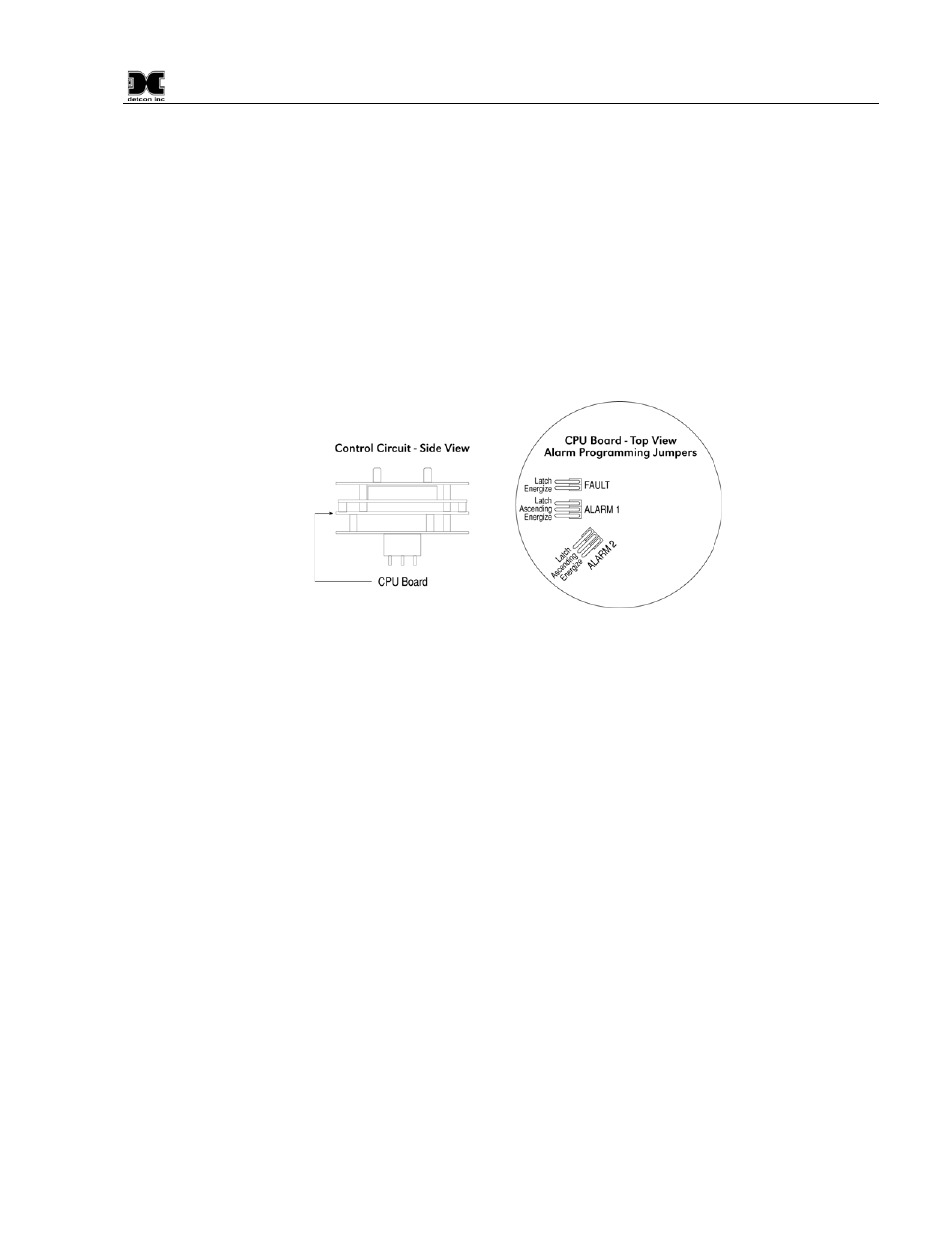
3.4 Relays and RS-485 Setup
Program the alarms via the gold plated jumper tab positions located on the CPU board (Figure 10). Alarm 1
and Alarm 2 have three jumper programmable functions: latching/non-latching relays, normally
energized/normally de-energized relays, and ascending/descending alarm set points. The fault alarm has two
jumper programmable functions: latching/non-latching relay, and normally energized/normally de-energized
relay. The default settings of the alarms (jumpers removed) are normally de-energized relays, non-latching
relays, and alarm points that activate during descending gas conditions.
Figure 10 Alarm Jumpers
If a jumper tab is installed in the latch position that alarm relay will be in the latching mode. The latching
mode will latch the alarm after alarm conditions have cleared until the alarm reset function is activated. The
non-latching mode (jumper removed) will allow alarms to de-activate automatically once alarm conditions
have cleared.
If a jumper tab is installed in the energize position, that alarm relay will be in the energized mode. The
energized mode will energize or activate the alarm relay when there is no alarm condition and de-energize or
de-activate the alarm relay when there is an alarm condition. The de-energized mode (jumper removed) will
energize or activate the alarm relay during an alarm condition and de-energize or de-activate the alarm relay
when there is no alarm condition.
If a jumper tab is installed in the ascending position that alarm relay will be in the ascending mode. The
ascending mode will cause an alarm to fire when the gas concentration detected is greater than or equal to the
alarm set point. The descending mode (jumper removed) will cause an alarm to fire when the gas
concentration detected is lesser than or equal to the alarm set point. Except in special applications, H
2
S
monitoring will require alarms to fire in “ASCENDING” gas conditions.
Any unused jumper tabs should be stored on the connector board on the terminal strip labeled “Unused
Jumpers”.
If applicable, set the RS-485 ID number via the two rotary dip switches located on the preamp board (see
Figure 11). There are 256 different ID numbers available, which are based on the hexadecimal numbering
system. If RS-485 communications are used, each sensor must have its own unique ID number. Use a
jeweler’s screwdriver to set the rotary dipswitches according to Table 1 Hexadecimal Conversion. If RS-485
communications are not used, leave the dipswitches in the default position, which is zero/zero (0)-(0).