3 electrical connections, Electrical connections, Figure 8 port identification – Detcon 1000 User Manual
Page 11
Mdl 1000 H2S E-Chem / Inst. Air
Model 1000 H2S E-Chem w Instrument Air
Rev. 1.1
Page 7 of 28
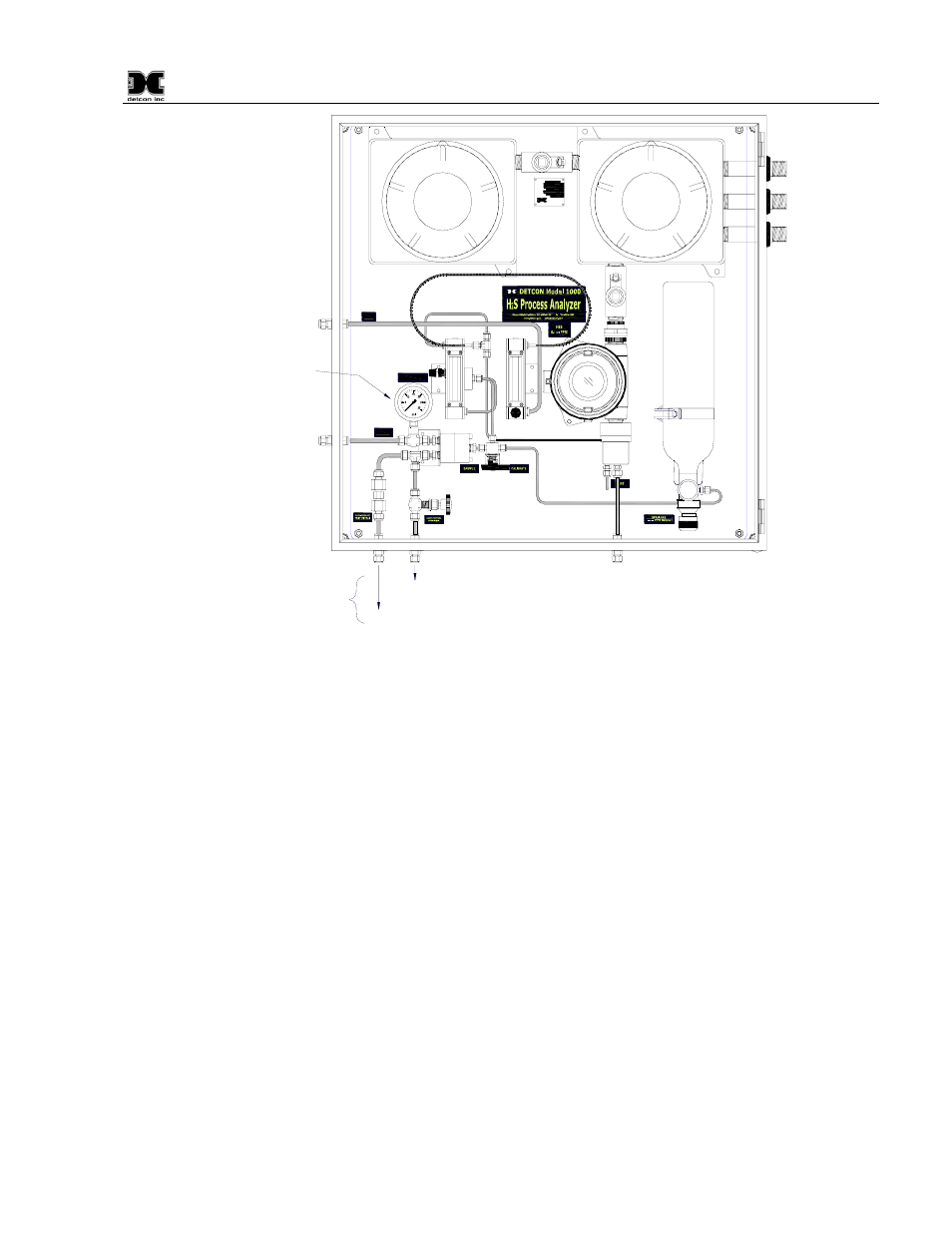
Instrument Air Inlet Port
Sample Inlet Port
Pressure Gauge
Sample Bypass and Liquid
Rejection Exhaust Vent.
Over Pressure Relief Vent
NOTE:
These may be
combined into a
single vent
Sample Calibrate
H
2
S Vent
Cal Gas
SAMPLE
FLOW
AIR
FLOW
INLET
SAMPLE
10 PSIG (CONSTANT)
SAMPLE PRESSURE
INLET
AIR
MODEL NO.
SERIAL NO.
INPUT VOLTAGE
FREQUENCY
CURRENT LOAD
AREA CLASSIFICATION
detcon inc.
3200 A-1 Research Forest Dr.
The Woodlands, TX 77381
www.detcon.com
PART NO.
Figure 8 Port Identification
2. Supply Instrument Air to the “Air Inlet” port (Figure 8). The instrument air should be regulated to
10±1psig.
3. Whenever possible, the Sample Bypass flow control valve of the Genie membrane filter should be used to
minimize the sample lag time between the sample tap and the analyzer location. It can also be used as a
means to exhaust condensed liquids in the sample line away from the Genie filter and prevent a “loss of
flow” condition. Set a flow of 100-200cc/min. and vent to a safe area using ¼” O.D. tubing.
4. Connect to the Over-pressure Relief valve and vent to a safe area. The pressure relief valve is set at
Detcon to open at 15-20psig. For convenience sake, the sample bypass and over-pressure relief can be
vented together.
5. Install a length of ¼" OD stainless steel tubing from the vent port to an area deemed safe for venting as
shown in Figure 8. Venting pressure should be in the range of 0±1psig and ambient pressure is highly
preferred.
3.3 Electrical Connections