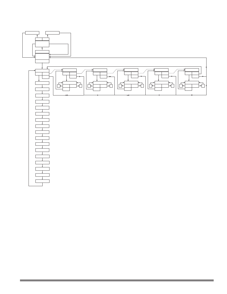
Figure 7, Oftware, Hart – Detcon PI-600 User Manual
Page 22: Alibration
3.7 S
OFTWARE
F
LOW
C
HART
3.8 C
ALIBRATION
Material Requirements
*
Detcon PN 943-003270-000 MicroSafe™ Programming Magnet
*
Detcon PN 943-000006-132 Calibration Adapter
*
Zero Air gas containing no VOC compounds
*
Span gas containing isobutylene in air. The cal gas concentration is recommended at 50% of range (which is the fac-
tory default) at a controlled f low rate of 200 cc/min. Example: for a Model PI-600 sensor with a range of 0-100ppm,
a test gas of 50 ppm isobutylene is recommended. For a sensor with a range of 0-10 ppm a test gas of 5 ppm is rec-
ommended, etc. Other concentrations can be used as long as they fall within 10% to 90% of range. See section
3.8.2 for details. Reference section 3.9-b-1 if you do not know the sensor target gas or range of detection.
3.8.1 Calibration Procedure - Zero
NOTE 1: Before performing a zero calibration, determine if there are any active VOC target gases in the area. If it can
be concluded that there are no active VOC gases in the area, then execute steps b) and c) below.
PI-600 Toxic Gas Sensors PG.22
NORMAL
OPERATION
CALIBRATION
PGM1 (3)
PGM2 (3)
1-ZERO 2-SPAN
LEGEND
PGM1 - program switch location #1
PGM2 - program switch location #2
(M) - momentary pass of magnet
(3) - 3 second hold of magnet
(30) - 30 second hold of magnet
INC - increase
DEC - decrease
# - numeric value
AUTO ZERO
AUTO SPAN
GAS RANGE
PGM1 (3) PGM2 (M)
VIEW PROG STATUS
PGM2 (3)
PGM1 (3)
PGM2 (30)
Software Version V#.#
PGM1 (M) PGM2 (M)
PGM1 (3)
CalLevel @ ##PPM
INC
DEC
PGM1 (3) PGM2 (M)
SET CAL LEVEL
PGM2 (3)
PGM1 (M) PGM2 (M)
PGM1 (3)
RESPFACTOR = X.XX
INC
DEC
PGM1 (3) PGM2 (M)
SET RESPONSE FACTOR
PGM2 (3)
PGM1 (M) PGM2 (M)
PGM1 (3)
ZERO OFFSET = X.X PPM
INC
DEC
PGM1 (3) PGM2 (M)
SET ZERO OFFSET
PGM2 (3)
PGM1 (M) PGM2 (M)
PGM1 (3)
SET ALM1 @ ##PPM
INC
DEC
PGM1 (3) PGM2 (M)
SET ALARM 1 LEVEL
PGM2 (3)
PGM1 (M) PGM2 (M)
PGM1 (3)
SET ALM2 @ ##PPM
INC
DEC
PGM1 (3) PGM2 (M)
SET ALARM 2 LEVEL
PGM2 (3)
ALM1 SET @ ##PPM
ALM2 SET @ ##PPM
ALM1 (Firing Direction)
ALM1 (Latch State)
ALM1 (Energize State)
ALM2 (Firing Direction)
ALM2 (Latch State)
ALM2 (Energize State)
FLT (Latch State)
FLT (Energize State)
SENSOR LIFE ##%
ZERO OFFSET = X.XX
RAW SIGNAL = X.XX V
CAL LEVEL @ ##PPM
485 ID SET @ #
Figure 7