Figure 5, Voc figure 6, Plug-in universal microprocessor control circuit – Detcon PI-600 User Manual
Page 21
3.6.4 Programming Magnet Operating Instructions
Operator interface to MicroSafe™ gas detection products is via magnetic switches located behind the transmitter face
plate. DO NOT remove the glass lens cover to calibrate or change programming parameters. Two switches labeled
“PGM 1” and “PGM 2” allow for complete calibration and programming without removing the enclosure cover, there-
by eliminating the need for area de-classif ication or the use of hot permits.
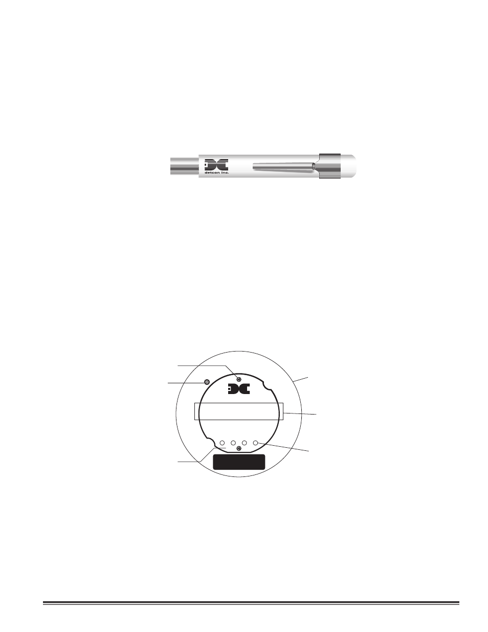
A magnetic programming tool (see f igure 5) is used to operate the switches. Switch action is def ined as momentary con-
tact, 3 second hold, and 30 second hold. In momentary contact use, the programming magnet is waved over a switch
location. In 3 second hold, the programming magnet is held in place over a switch location for 3 or more seconds. In
30 second hold, the programming magnet is held in place over a switch location for 30 or more seconds. Three and
thirty second hold is used to enter or exit calibration and program menus while momentary contact is used to make
adjustments. The location of “PGM 1” and “PGM 2” are shown in f igure 6.
NOTE: If, after entering the calibration or program menus there is no interaction with the menu items for more than
30 seconds, the sensor will return to its normal operating condition.
PI-600 Toxic Gas Sensors PG.21
Magnetic Programming Tool
Figure 5
detcon inc.
Program Switch #2
FLT
ALM
1
CAL
MicroSafe™ Gas Sensor
HOUSTON, TEXAS
PGM
2
PGM
1
ALM
2
MODEL
PI-600
CONTRAST
Alarm & Cal LEDs
Program Switch #1
Menu Driven Display
Plug-in Universal Microprocessor
Control Circuit
Display Contrast Adjust
UNIVERSAL
TRANSMITTER
PPM
0
VOC
Figure 6