Service and maintenance, Calibration frequency, Visual inspection – Detcon IR-700 User Manual
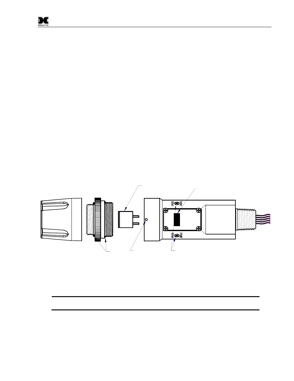
Page 33: Condensation prevention packet, Replacement of ir plug-in combustible gas sensor, Figure 15 sensor assembly, 1 calibration frequency, 2 visual inspection, 3 condensation prevention packet, 4 replacement of ir plug-in combustible gas sensor
Model IR-700
IR-700 Instruction Manual
Rev. 3.1
Page 29 of 40
5. Service and Maintenance
5.1 Calibration Frequency
In most applications, quarterly to biannual zero and semi-annual to annual span calibration intervals will
assure reliable detection.
However, industrial environments differ.
Upon initial installation and
commissioning, close frequency tests should be performed, weekly to monthly.
Test results should be
recorded and reviewed to determine a suitable calibration interval.
5.2 Visual Inspection
The Sensor should be inspected annually. Inspect for signs of corrosion, pitting, and water damage. During
visual inspection, the Splash Guard should be removed and inspected to insure that it is not blocked. Examine
the porous 316SS flame arrestor within the sensor’s bottom housing for signs of physical blockage or severe
corrosion. Also, inspect inside the Junction Box for signs of water accumulation or Terminal Block corrosion.
5.3 Condensation Prevention Packet
A moisture condensation packet should be installed in every explosion proof Junction Box. The moisture
condensation prevention packet will prevent the internal volume of the J-Box from condensing and
accumulating moisture due to day-night humidity changes. This packet provides a critical function and should
be replaced annually. Detcon’s PN is 960-202200-000.
Plug-in Replacable
Combustible
Hydrocarbon Sensor
M
O
D
E
L
IR
-7
0
0
d
e
tc
o
n
in
c
.
L
E
L
S
e
n
s
o
r
Splash Guard
Housing Bottom
Assembly
O-Rings
d
e
tc
o
n
in
c
.
Lens and LCD
Display
Housing Bottom
Locking Set-Screw
Magnetic
Programming
Switches
Intelligent Transmitter Module (ITM)
Micro-Processor controlled circuit
encapsulated in an explosion proof
housing.
Figure 15 Sensor Assembly
5.4 Replacement of IR Plug-in Combustible Gas Sensor
a) Remove power to IR-700 sensor by lifting the + 24 VDC wire in J-Box.
NOTE: It is necessary to remove power while changing the plug-in combustible gas sensor in
order to maintain area classification.
b) Use a M1.5 Allen wrench to release the locking setscrew that locks the ITM and bottom housing
together (One turn will suffice – Do not remove setscrew completely).
c) Remove splashguard. Unthread and remove the Bottom Housing from the ITM.