Analog output, Limit & frequency output, Rt-30ex flow transmitter – AW Gear Meters RT-30EX User Manual
Page 11: Operation and programming manual
RT-30EX Flow Transmitter
Operation and Programming Manual
11
RT-30EX User Manual, Rev. 1.7 02/07/2012
OPTO-
ISOLATOR
50mA Polyfuse 3, 11, 13
4, 12, 14
(+)
(-)
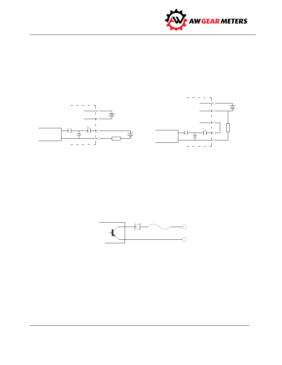
Analog output
The isolated 16-bit 4-20mA output can be wired for use with Loop powered inputs or for ground
referenced inputs. The analog signal has an LED in series which varies in intensity as the mA signal
varies. This can be used for troubleshooting purposes.
When using the analog signal with inputs used with loop powered signals, it is important to note that
the RT-30EX still requires a separate power supply to power the unit as shown Figure 5 below.
When using the analog signal with ground referenced inputs, jumper pins 8 and 9 together as shown in
Figure 6 above. Analog signal is taken from pin 10 and returns to pin 2 (supply ground).
Limit & frequency output
Three opto-isolated NPN open-collector outputs can sink or source depending on connection. Attention
must be paid to polarity of connections. See page 7 for electrical specification and page 9 for Limit 1,
Limit 2 & Frequency pin-out pairing.
R sense
ANALOG
CIRCUIT
0.01uF
9
10
5
6
SUPPLY
VOLTAGE
9-24 Vdc
(Class 2)
(+)
(-)
9-24 Vdc
(Class 2)
(+)
(-)
RT-30EX
Figure 5: Loop powered analog output
Figure 6: Ground referenced analog output
Figure 7: Limit1, Limit 2 & Frequency outputs
R sense
ANALOG
CIRCUIT
0.01uF
9
10
5
6
SUPPLY
VOLTAGE
9-24 Vdc
(Class 2)
(+)
(-)
RT-30EX
8