Rt‐10 flow monitor, Rt-ex10, Standard configurations – AW Gear Meters RT-10 User Manual
Page 8: Dimensions, Operation and programming manual
RT‐10 Flow Monitor
Operation and Programming Manual
7
FIB ER- O PTIC
O UTPUT TO
O PTV- 2 0
RT-EX10
SR# RT001500
FO P Fib e r- o p t ic In p u t/O u tp u t
HUB
TR Se rie s
JV, H PM & TRG
FIB ER- O PTIC
IN PUT FROM
FO P- 2 0 O R
FO P- 3 0
SEN SO R N O SE
SPRIN G LO A D ED
HUB A D A PTO R
RT-EX10
SR# RT001500
TURB IN ES
FO R TR SERIES
M A G SEN SO R
SR# RT001500
RT-EX10
SR# RT001500
RT-EX10
5 /6 4 " HEX KEY
SW IVEL
FITTIN G
SR# RT001500
RT-EX10
4 .5 in .
M A GN ET
W A N D FO R
PRO GRA M M IN G/
D ISPLA Y
SELEC TIO N
5 in .
Ø .3 in .
5 in .
5 in .
2 .3 in .
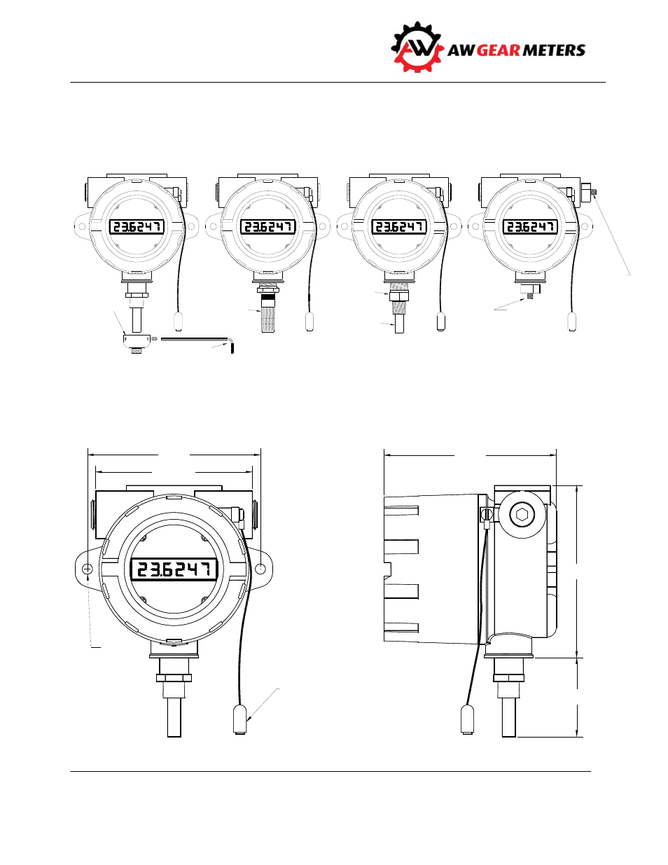
Standard Configurations
The illustration below shows standard, TR series, HUB, and fiber optic variations of the RT‐10 Flow
Monitor.
Dimensions