Rt‐10 flow monitor, Operation and programming manual – AW Gear Meters RT-10 User Manual
Page 10
RT‐10 Flow Monitor
Operation and Programming Manual
9
SR# RT001500
RT-EX10
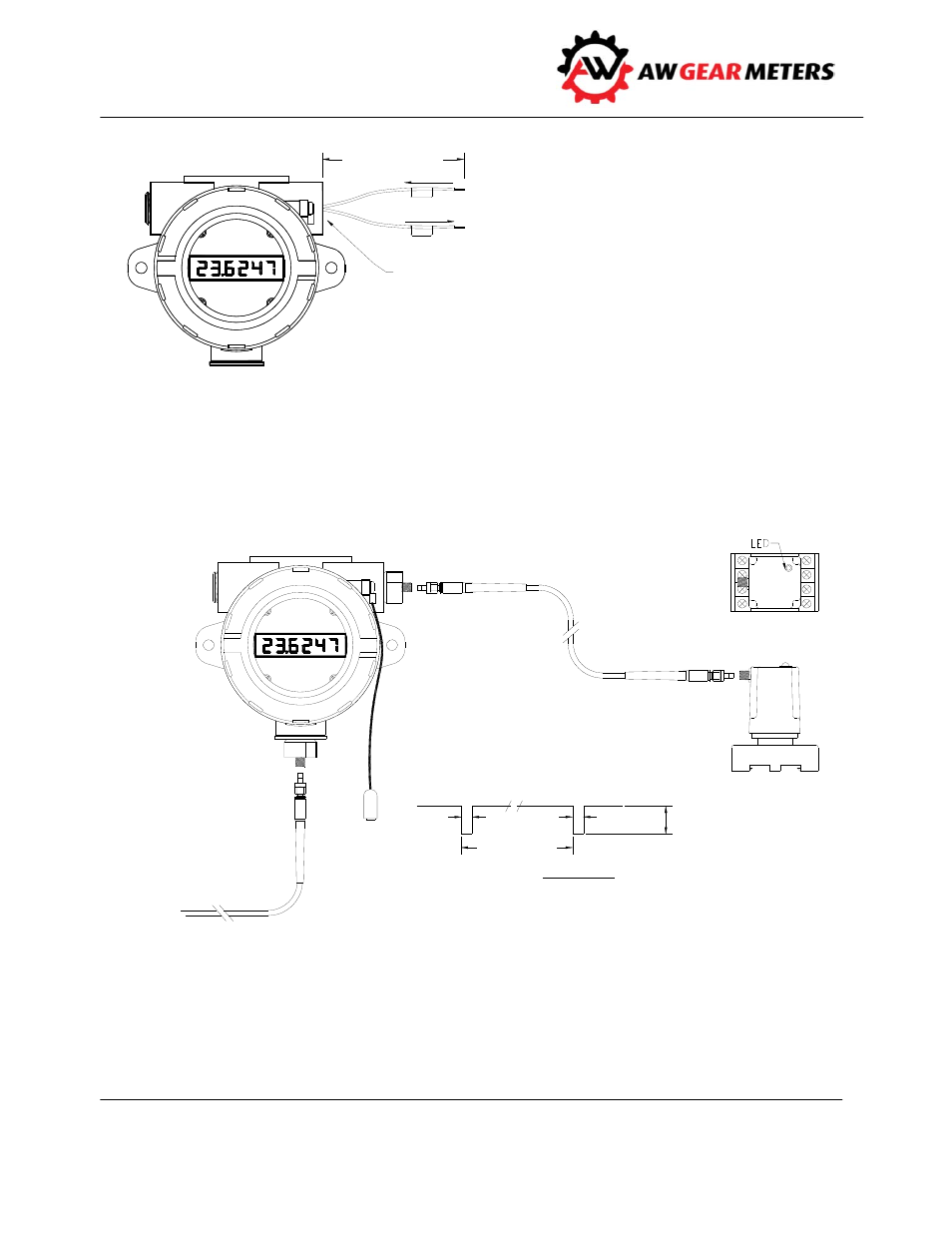
PIGTA IL LEA D S
m A +
m A -
1 /2 " N PT
(LA B ELLED )
m A +
m A -
LO O P- PO W ERED
TW O - W IRE
4 - 2 0 m A O UTPUT
Fiber‐Optic Systems (fiber‐optic input/output models only)
Fiber optic input models accept optical signals from AW Gear Meters FOP‐20 or FOP‐30 fiber optic
transmitters using AW Gear Meters fiber optic cable. Fiber‐optic output models transmit a scaleable 0‐
100 Hz signal via fiber‐optic cable to the AW Gear Meters OPTV‐20 or OPTV‐CM fiber optic receiver.
FIB ER- O PTIC
C A B LE
+ 7 - 2 0 VD C - 1
O PTIC A L REC EIVER GRO UN D - 8
3
4
5
6
C O M M O N - 2
SQ UA RE W A VE SIGN A L O UT - 7
FIB ER- O PTIC
C A B LE
RT-EX10
SR# RT001500
FO P Fib e r- o p t ic In p u t /O u t p u t
FRO M FO P- 2 0 O R FO P- 3 0
O PTV- 2 0
O R
O PTV- C M
O PTV O UTPUT
PULSE TIM E
~ 1 m s*
~ 1 m s*
1
PULSE TIM E
A M PLITUD E O UT:
A PPRO X. SUPPLY VO LTA GE,
D EPEN D S O N LO A D
FREQ UEN C Y =
* 6 m s FO R O PTV- C M
Figure 2: Fiber‐Optic Sytstems
Figure 1: Loop‐Powered Analog Output