Operation, Rt‐10 flow monitor, Display modes – AW Gear Meters RT-10 User Manual
Page 11: Operation and programming manual
RT‐10 Flow Monitor
Operation and Programming Manual
10
Operation
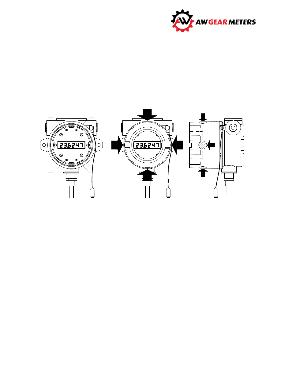
Use the buttons on the face plate when the cover is off, or the magnet wand when the cover is on, to
affect mode and program changes and to reset total.
The magnetic switches are located at the 3, 6, 9 and 12 o’clock positions on the side of the housing.
Markers on the faceplate of the device indicate the function of each position. Touch the side of the
magnet wand to the appropriate location to activate a magnetic switch.
Display Modes
The RT‐10 has three main display modes:
RATE
TOTAL
CLOCK
Change the Display Mode by using the DN/MODE button when the cover is open or by using the
external magnetic switch.
The RT‐10 automatically generates two additional displays: SLEEP and LO BATTERY. See below.
SR# RT001500
RT-EX10
M O D E
1
1
4
SR# RT001500
UP
SEL
ENT
RT-EX10
UP
SEL
ENT
DN/
MODE
DN/
MODE
1
1
4
D N /M O D E
UP/RESET
EN T
SEL
D N /
R ES E T
U P /
EN T
S E L
M A GN ETIC SW ITC H LO C A TIO N S
B UTTO N LO C A TIO N S
TO UC H SID E O F
M A G N ET W AN D TO
HO USIN G IN SPEC IFIED
LO C A TIO N S TO
A C TIVA TE SW ITC HES
Figure 3: Button and Magnetic Switch Locations