AST AST46DS Operating Instructions User Manual
Page 2
TM
TM
www.astsensors.com (973) 448-1901
www.astsensors.com (973) 448-1901
PROCESS CONNECTION INSTALLATION
The standard process connection for the AST46DS is ½” NPT male. Use the
7/8” hex above the thread of the process connection to install into the process.
Do not use the body / housing for installation.
ELECTRICAL INSTALLATION
WARNING
: EXPLOSION HAZARD
Do not disconnect equipment unless power has been switched off or the area
is known to be non-hazardous. This equipment must be powered by a Non-
hazardous live source in accordance with CAN/CSA-C22.2 No. 61010-1-04 eg.
limited energy source, or a Class 2 Source.
Please review the following wiring instructions. For U.S. installations, product
case ground screw on the interior or exterior of the housing must be bonded to
ground according to Article 501 & 505 of the NEC.
Recommended Wire Gauge: 18-22 AWG
Remove rear cover by hand to access terminal blocks.
•
Run wire through either conduit connection and feed toward the terminal blocks.
•
Conduit should be installed over wire / cable per electrical code requirements.
Use a Philips Head screw driver to loosen terminal screws.
•
Connect wires to the proper terminal according to chart and tighten screw.
•
Ensure either the internal or exterier case ground screw is
•
bonded to ground
according to Article 501 & 505 of the NEC.
Install conduit plug if one side of electrical connection is unused.
•
Close Cover.
•
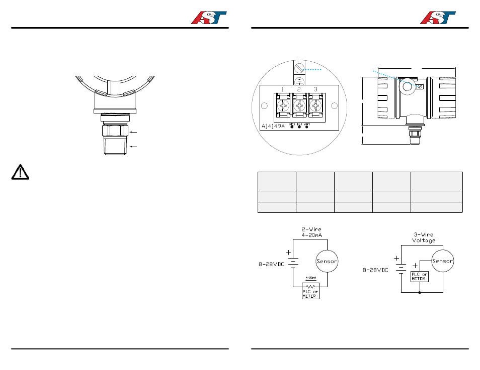
WIRING INFORMATION
Output Type
Pin 1
Pin 2
Pin 3
Electrical Power
Requirement
1-5V
+V
-V
Signal Output
8-28VDC
4-20mA
+Signal
- Signal
Not Connected
8-28VDC
PIN 1
PIN 2
PIN 1
PIN 2
PIN 3
7/8’’ Hex
1/2’’ NPT Male
FIELD SERVICE
The AST46DS has no field serviceable parts. For technical issues or questions,
please contact the factory:
1/2” NPTF
1/2” NPTF
6.535
4.134
1.556
3.543
4.173
1.575
case ground screw
TERMINAL BLOCK OUTLINE