AST AST5100 Datasheet User Manual
Low pressure differential transmitter, Applications electrical data, Performance @ 25°c (77°f)
TM
American Sensor Technologies
•
450 Clark Dr., Mt. Olive, NJ 07828
•
phone (973) 448-1901
•
fax (973) 448-1905
•
email: [email protected]
* Accuracy includes non-linearity, hysteresis & non-repeatability
Liquid Level Control including Bubbler
systems
Climate Control
Energy Management
Air-fuel Ratio including Measurement for
Furnaces
Vapor Recovery
Leak Detection
Air or liquid Filtration
Flow Measurement
Applications
Electrical Data
Output
4-20mA
0-5V Three Wire
Excitation
10-28VDC
10-28VDC
Output Change with Input Voltage Change
-
<0.1% from 10 to 32 VDC
Current Consumption:
-
< 10mA
Bandwidth
5Hz
5Hz
Output Noise:
< 0.0035mA, RMS
< 1mV, RMS
Zero Offset:
< ± 1% FS
< ± 1% FS
Span Tolerance:
< ± 1.5% FS
< ± 1.5% FS
Output Load:
0-800 Ohms@10-28 VDC
5k Ohms, min.
Reverse Polarity
Yes
Yes
Performance @ 25°C (77°F)
Accuracy
<±1.0% of FS
Stability (1 year)
±0.5%FS, typ
Burst Pressure
2000 PSI
Pressure Cycles
>100,000 Cycles
Environmental Data
Temperature
Operating
-40 to 80°C (-40 to 176°F )
Storage
-40 to 100°C (-40 to 212°F)
Thermal Limits
Compensated Range 0 to 55°C (32 to 131°F)
TC Zero
<±1.5% of FS
TC Span
<±1.5% of FS
Benefits
Accurate Low Pressure Measurement
Excellent Repeatability
Wide Range of Liquids and Gases
including: Water, Natural Gas,
Hydrocarbon Fuels, Air and Non-Corrosive Gases
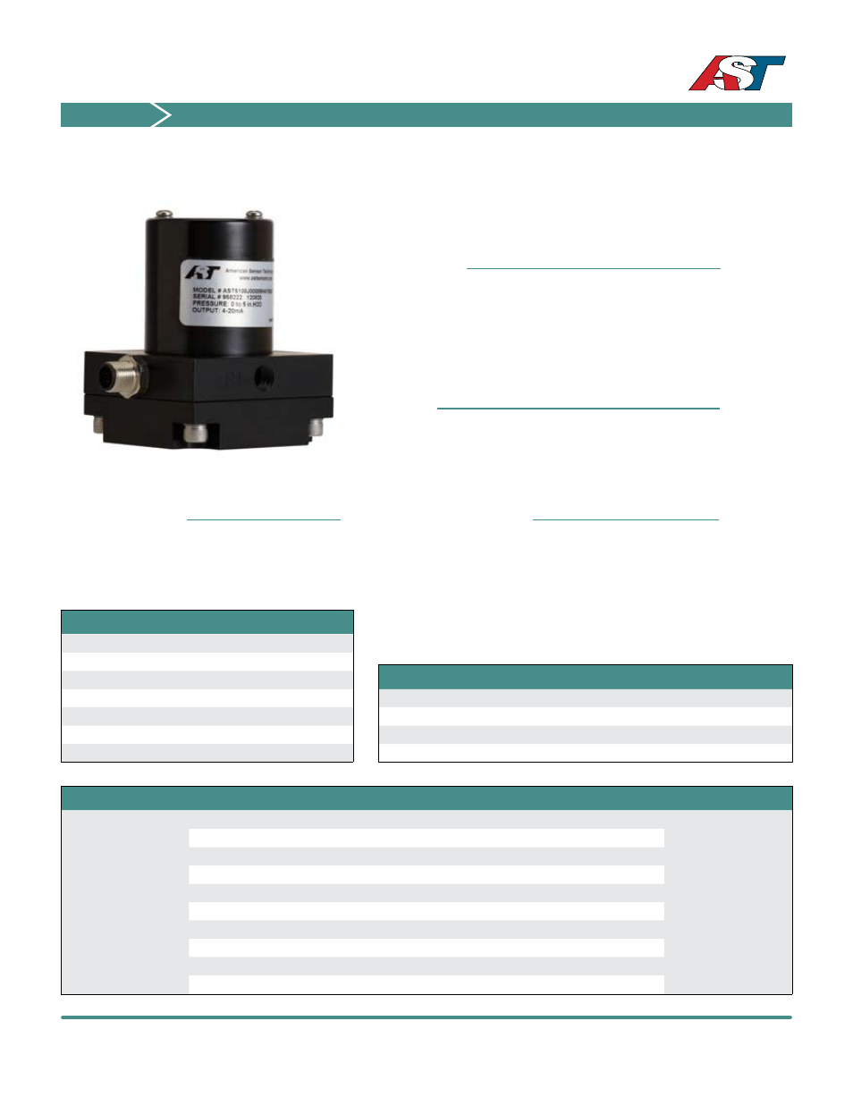
The AST5100 Wet - Wet Differential Pressure transmitter is your accurate pressure
sensing device for low differential pressure. With a differential pressure range as
low as 0 to 5” water column (12.5mbar), this product can be used to measure flow
across an orifice, differential across a filter, tank level, or gauge pressure. Using
LVDT technology and AST’s advanced electronics, the AST5100 delivers accurate,
repeatable measurements.
AST5100
Low Pressure Differential Transmitter
Wetted Materials
Nickel Alloy 52, Ni-Span C, Viton, 304 Stainless Steel,
Aluminum 6061, RoHS Solder, Loctite 680 (meets NSF61)
Installation Guidelines
The AST5100 must be mounted on a flat surface within ± 15° to the ideal 0° plane to
maintain specifications. Do not Overtighten the pressure connections or insert any ob-
jects in P1 or P2 to avoid damaging the sensing element. When using isolation valves,
both should be mounted close to the sensor. For liquid level and wet applications,
install bleed screw adapters close to P1 and P2 so that trapped air can be purged if
needed. For optimum performance, always make sure pressure is equalized within the
pressure range chart ranges. The AST5100 has asymmetric protection on P1 and P2.