Sdd d – Triton RL5000 X2 Series Installation Manual User Manual
Page 32
3 2
M
ODEL
RL5000 (X2) I
NSTALLATION
G
UIDE
I
NSTALLING THE
SDD D
ISPENSING
M
ECHANISM
The SDD dispensing mechanism is shipped inside the
cabinet of the RL5000 security cabinet in its own
container. Remove it from inside the cabinet before the
ATM is bolted to the floor.
1.
Refer to Figure 1. Unlock and open the control
panel. Verify that the power switch is in the OFF (0)
position. Close the control panel.
2.
Remove the packing material from the ends of the
dispenser data and power cables that are hanging
inside the cabinet.
3.
Unpack and remove the ATM mechanism from its
shipping container.
4.
Pull the cassette tray out to its fully extended
position as shown in Figure 2.
5.
Pick up the dispensing mechanism and place it on
the cassette tray. Leave enough room to easily
access the back of the dispensing mechanism so it
can be connected to the cables coming from the
ATM.
Figure 1. Power switch on left side of
power module.
Figure 2. SDD dispenser tray pulled
out to extended position.
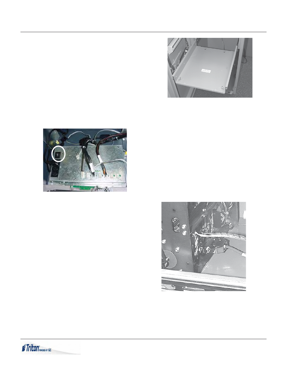
6.
Refer to Figure 3. Connect cable 9600-0043 to the
DB25 connector (PL6) on the rear of the dispenser
mechanism. Secure the DB25 cable to the
dispenser with two screws attached to the
connector. Insert the Molex power plug attached
to cable 9600-0013 into the connector marked PL2.
This plug is keyed so that it can only be inserted
in one direction.
Figure 3. Connections for DC power
and communications.