Tele Vue Tele-Pod Sky Tour User Manual
Tele vue, Tele-pod/sky tour instructions
32 Elkay Dr., Chester, NY 10918 (845) 469-4551 www.televue.com
Tele Vue
V i s i o n a r y
TELE-POD/SKY TOUR INSTRUCTIONS
Parts Check List
•
Tele-Pod Mount (head with attached encoders and tripod)
•
Mount Handle
•Eyepiece Caddy Set [with (4) ¼"-20 button head screws & (4) Thumb Knobs
attached and (2) 2"-1¼" Caddy Inserts installed]
•
Sky Tour Caddy Plate
•
Sky Tour Computer
•
Sky Tour Operating Guide & Sky Tour Database
•
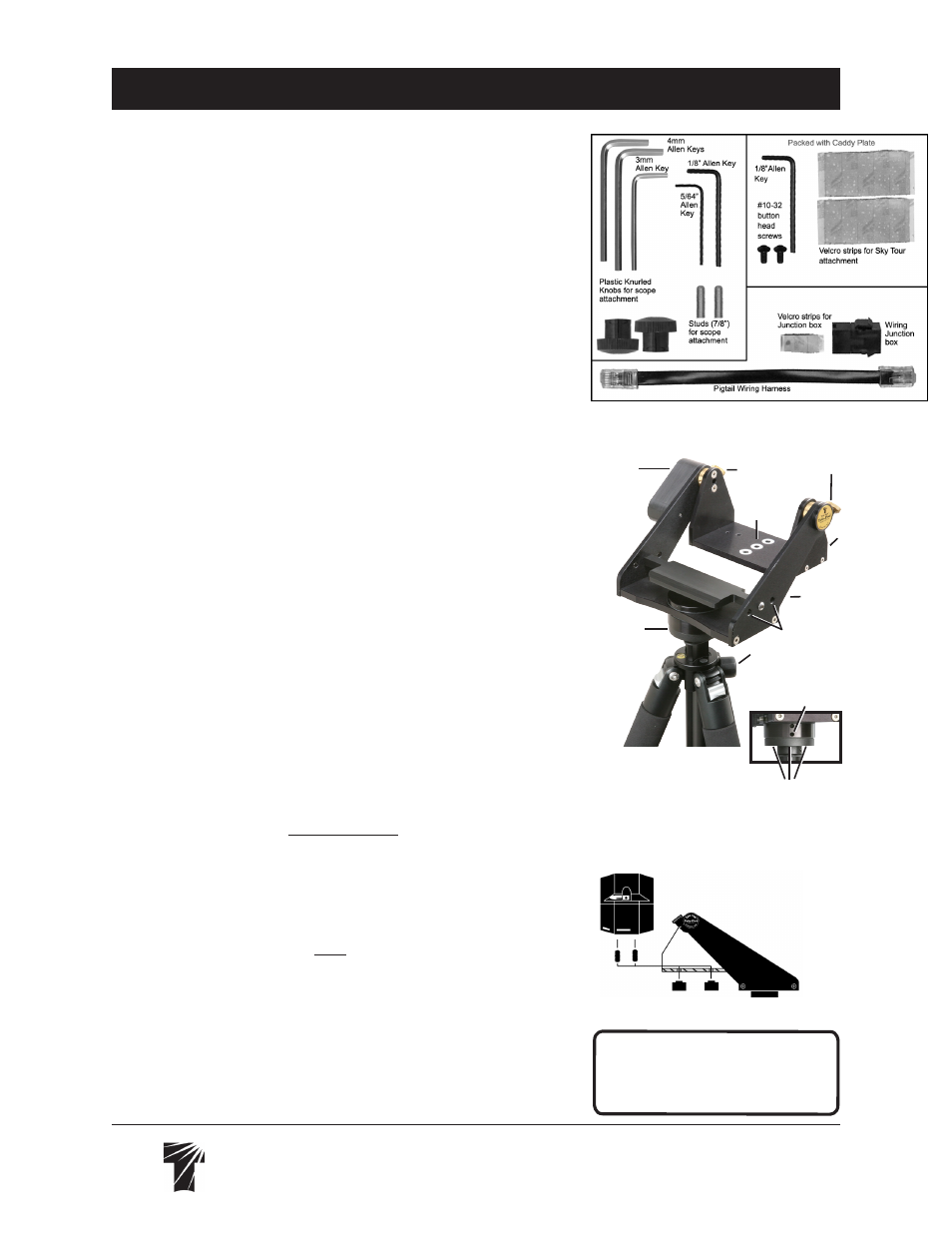
Small-Parts Bags include: (1) Pigtail Wiring Harness, (1) Wiring Harness Junction
box, (1) Velcro strip for Junction box, (2) Studs for scope attachment, Allen Keys:
[(1) 1/8" , (1) 5/64" Allen Key, (1) 3mm, (2) 4mm], (2) Plastic Knurled Knobs
for scope attachments, (2) #10-32 button head screws for Sky Tour Caddy Plate
attachment, (1) 1/8" Allen for Caddy Plate attachment, (2) Velcro strips for Sky
Tour attachment
INTRODUCTION
Thank you for purchasing the Sky Tour equipped, Tele-Pod Mount. The lightest, sim-
plest travel mount with digital setting circles you can find. The Tele-Pod combines
the size, weight and flexibility of a photo-tripod with the smooth, balanced altitude/
azimuth motions of our yoke and cradle mount head. The addition of the Sky Tour
computer greatly enhances your fun and capability. This instruction sheet covers
the basic set-up and operation of the mount. Please refer to the Sky Tour Operating
Guide for specific instructions on use of the computer.
COMPONENTS
The Tele-Pod consists of the mount head with attached encoders and main wiring
harness, and tripod. The head supports the scope and provides both vertical and
horizontal motions. It features smooth operating altitude and azimuth bearings, and
a Delrin scope stop in case the objective end accidentally “nose-dives.”
The tripod supports the head and allows height adjustment of the scope. The tripod
legs have rubber feet. See separate instruction sheet for more features of the tripod.
The Eyepiece Caddy Set mounts to the Yoke arms of the Tele-Pod head and
provides a place to put 5 eyepieces. The Sky Tour Caddy Plate attaches to either
the left or right Caddy bracket, which places the computer at your fingertips.
Familiarize yourself with the parts on the assembly photos for easy reference
and you will quickly learn how to put your Tele-Pod to best use.
TRIPOD SET-UP
WARNING: If setting up on a slope, ensure that the tripod legs are extended so
that the head is approximately level with the horizon. Failure to do so could cause
the telescope to tip over! This risk increases when using larger, longer scopes.
1) Loosen the top leg clamps on the tripod.
2) Extend each leg so that the mount head is slightly above the desired height and
approximately level with the horizon.
3) Tighten leg clamps.
4) Spread all three tripod legs to the first click-stop and the mount head should be
at the desired height.
4a) If you need the head higher, loosen the center column’s height adjustment
lock knob and lift to the desired height. Note that the Tele-Pod’s vibration dampening
is best when the center column is not extended.
5) Follow instructions packaged with handle to attach it to the mount.
6) Note: Mount head can be moved to other Tele Vue tripods or camera tripods
by using the 5/64" Allen to loosen lower set screw on Azimuth bearing plate. Flip
over and use 3mm Allen to back off 3 small set screws on flange base. Normally
the bearing plate and flange set screws are tight to prevent unscrewing of mount
head as mount is turned in azimuth. Now unscrew the Tele Pod Head.
Tele-Pod Mount as Packaged
Altitude
Encoder
Assembly
Delrin Azimuth
encoder housing/
scope stop
Mounting Holes on
each Yoke arm for
Eyepiece Caddy Set
Loose Parts in Bags
WARNING:
Rotating the Tele-Pod
head while the azimuth tension knob
is tightened could cause the azimuth
bearing to unscrew and separate.
Telescope Attachment Diagram
Yoke
Cradle
Altitude Tension Knobs
Stud
Clearance
Holes
Height Adjustment
Lock Knob
Azimuth
Bearing Plate
Azimuth Bearing Plate
Lower Set Setscrew
Set Screws on
Flange Bottom