Tele vue – Tele Vue Encoder User Manual
Page 2
32 Elkay Dr., Chester, New York 10918 (845) 469-4551 www.televue.com
Tele Vue
V i s i o n a r y
Azimuth Encoder Assembly
Azimuth Encoder Assembly
Azimuth Encoder Assembly
Azimuth Encoder Assembly
Azimuth Encoder Assembly
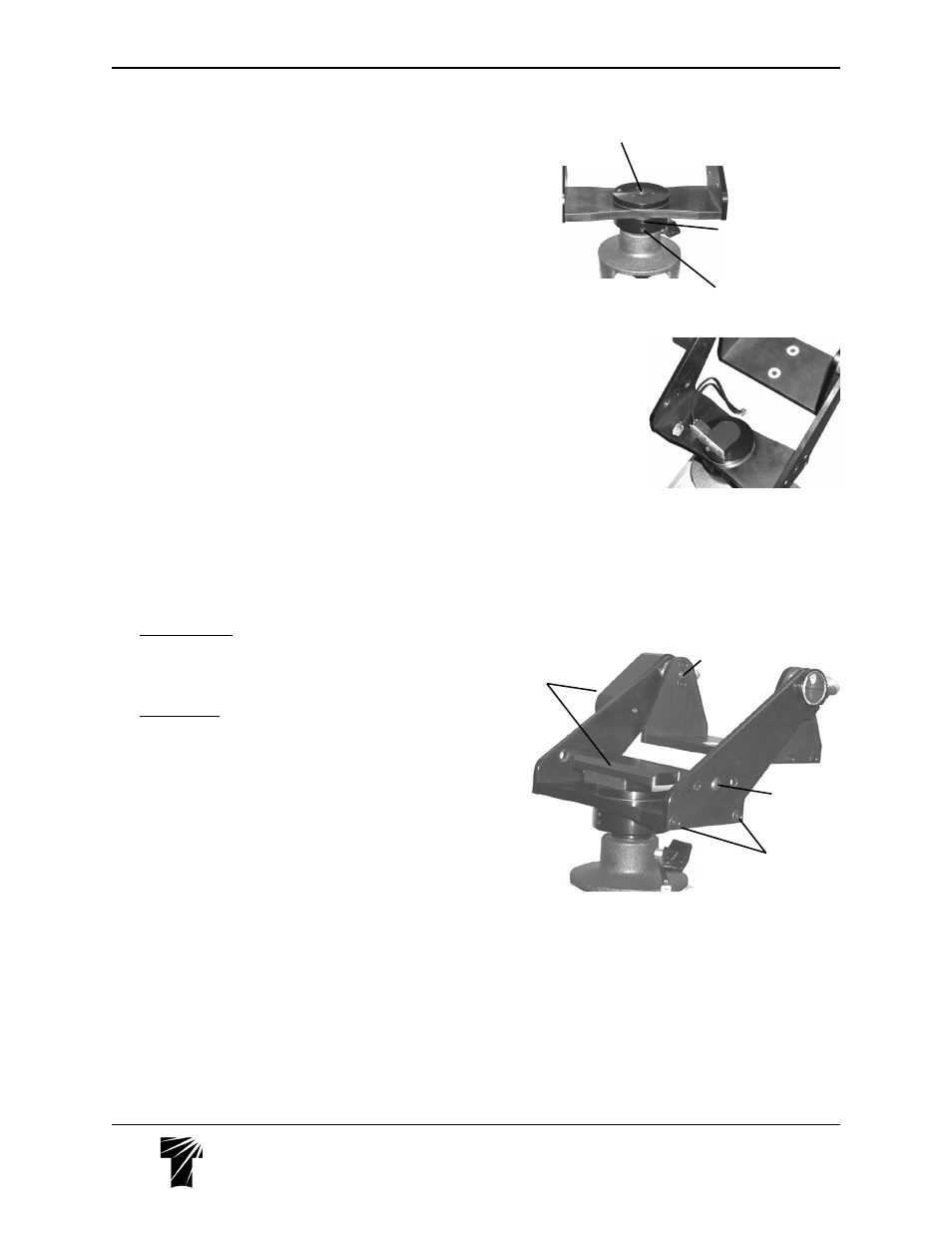
9) On the Yoke, unscrew both the original Delrin Scope Stop and Azimuth
Tension Knob from the center of the azimuth bearing.
10) Check the upper threaded hole in the lower azimuth bearing base for a set-
screw. If no set-screw is found, use the #8-32x3/4" provided in the parts bag.
11) Connect the azimuth lead of the Main Wiring Harness to the Azimuth
Encoder.
12) Press the Azimuth Encoder shaft down into the hole in the center of the
azimuth bearing.
13) With the 5/64 Allen key, lock the set-screw against the az. encoder shaft.
14) Rotate the encoder so the wiring harness terminal faces the Altitude Encoder
and route the remaining terminals out the back of the Yoke, under the cradle.
(See photo , right.)
15) Loosen both of the 10-32x1/2” flat head screws which hold either of the
yoke arms onto the base plate a couple of turns (it doesn’t matter which arm).
Slide the Azimuth Encoder Cover down between the Yoke Arms so that the
screw holes line up with the middle of the three clearance holes in the Yoke
Arms. The Azimuth Encoder Cover will fit only one way over the Azimuth
Encoder: make sure the encoder is aligned properly with the recess in the cover
before pressing it on. Do not force the cover onto the encoder; the encoder will
have a snug fit into the cover cut-out.
If it is too difficult to achieve this alignment, remove the encoder (see the section
on Removing and Reinstalling encoders), insert the encoder body into the recess
in the cover and attempt to install the encoder and cover as a unit. Again, do not
force the encoder. Retighten the set screw.
16a) Gibraltar5 mounts: place the spacers from the STS-5002 kit between the
ends of the Delrin azimuth bar and the insides of the yoke arms. Thread the 10-
32x1¼” button head screws provided in the kit into each side to hold the
Azimuth Encoder. Continue with step 16c.
16b) All other mounts: thread a 10-32x3/8 button head screw into each side
to hold the Azimuth Encoder Cover in place. Continue with step 16c.
16c) Tighten button head screws with the 1/8 Allen key while pressing down
on the cover. Once the cover is in place and the appropriate button head
screws are threaded a few turns into the ends of the arms of the encoder cover,
retighten the flat head screws on the yoke arm until they just barely bottom out.
Do not tighten them yet.
Hook a finger under one arm of the azimuth cover and pull it up (away from the
base plate) while tightening its round head screw. Repeat with the other arm.
Retighten the flat head screws the rest of the way.
17) Connect the altitude lead of the Main Wiring Harness to the Altitude
Encoder.
If you have the Eyepiece Caddy Set, skip instruction 18 and follow the
instructions in the next section.
18) If you do not have the recommended Eyepiece Caddy Set with the Sky
Tour Mounting Plate, connect the remaining lead of the Main Wiring Harness
to the Sky Tour Computer.
19) Follow the instructions provided with the Sky Tour for computer operation.
CONTINUED NEXT PAGE
Original scope stop removed,
reveals hole for Azimuth Encoder
Screw hole for
#8-32x3/4" set screw.
Screw drops in, threads
start deep within the hole.
Screw hole for Panoramic
attachment post
Azimuth encoder in
position. Note how
Main Wiring Har-
ness is draped
through the Yoke
and Cradle
#10-32x3/8"
button head screw
(or #10-32x1¼"
for Gibraltar5)
End of Altitude
Encoder Shaft
#10-32x1/2"
flat head screws
Both encoder
assemblies
installed.