Step 4 electrical connections, Step 5 testing of pump operation, Step 3 installation of the discharge piping – Star Water Systems S1585 User Manual
Page 4
4
© Copyright 2008. All rights reserved.
BATTERY
RED LEAD
TO POSITIVE(+)
TO NEGATIVE(-)
BLACK LEAD
SWITCH
CUT AWAY OF SUMP PIT
RED LEAD
TO POSITIVE(+)
MOTOR
CHARGER
NEGATIVE(-)
BATTERY TERMINAL
BATTERY TERMINAL
POSITIVE(+)
OUTLET
ALARM
BLACK LEAD
TO NEGATIVE (-)
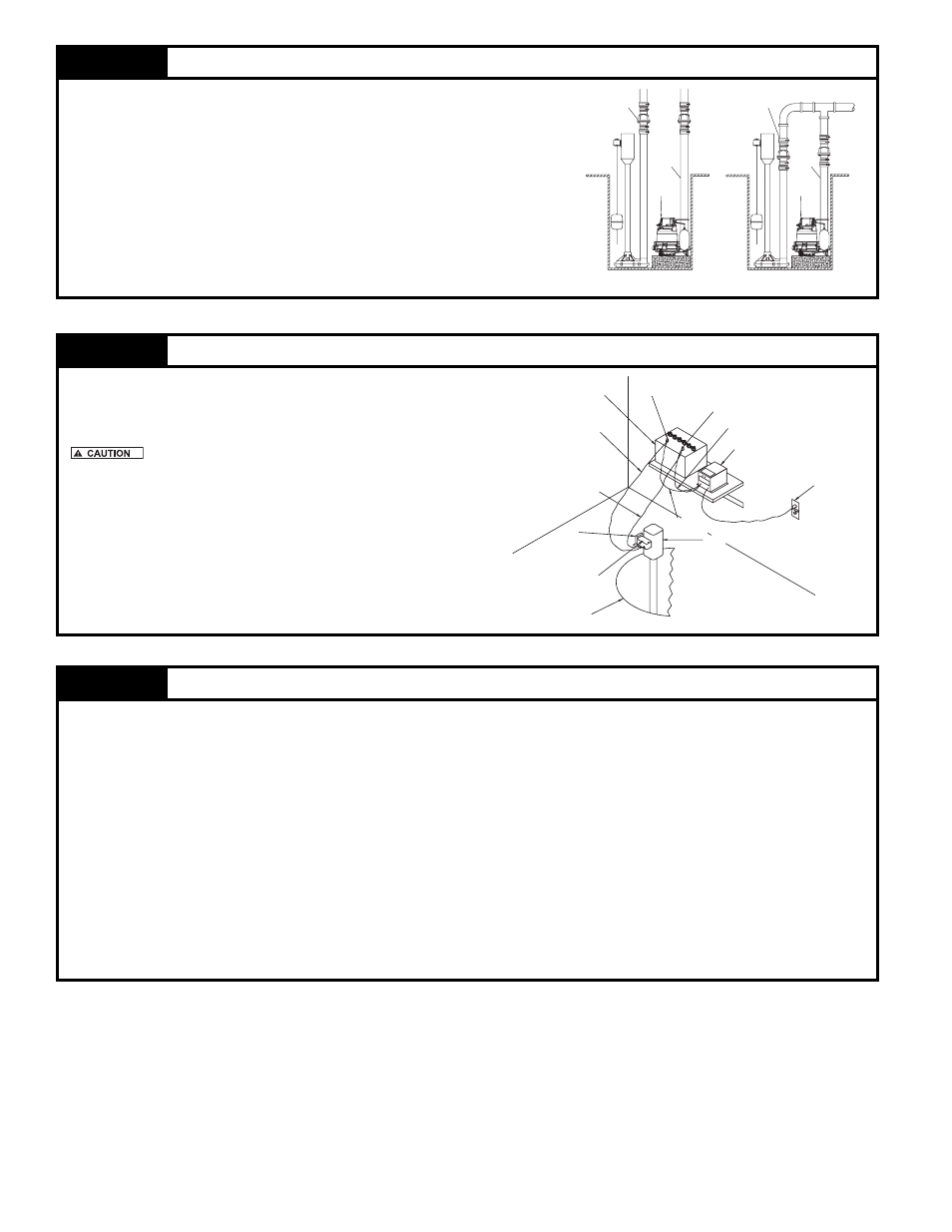
PRIMARY PUMP
DISCHARGE
MAIN
CHECK VALVE
LINE
PRIMARY PUMP
CHECK VALVE
DISCHARGE
LINE
MAIN
OR
STEP
4
Electrical Connections
4.1) Complete electrical connections as shown in Fig ure 4.1.
4.2) Proceed to STEP 6.
Do not place battery or charger directly on ground. If the
battery or charger must be placed directly on the ground, then place
a piece of wood between the units and the ground. Do not put the
charger on top of the battery.
Figure 4.1
STEP
5
Testing of Pump Operation
6.1) Unplug the primary pump so that it does not start.
6.2) Fill pit with water until the Aquanot® starts.
6.3) Verify that the pump starts and stops at the desired on/off points.
6.4) Verify that there are no leaks in the discharge line.
6.5) If adjustment is necessary, raise or lower the appropriate stop(s) according to STEP 2.
IMPORTANT: Spacing between upper and lower stops determine amount of water removed from pit.
6.6) If
the pump is not operating properly after following the above steps, refer to the Troubleshooting guide on page 8.
6.7) When
fi nished testing plug primary pump back into AC receptacle.
STEP
3
Installation of the Discharge Piping
3.1) Assemble the discharge pipe into the pump as shown in
Figure 3.1.
IMPORTANT: In order for this installation to work properly, a check
valve must be installed onto the discharge line.
( Recommend the following Star check valve, #KH34.
Some local codes require union check with ball valve.
Figure 3.1
SK1783
SK1778