Air distribution valve assembly drawing – SANDPIPER S05 Non-Metallic User Manual
Page 14
520-211-000
3/03 Rev C
Model S05 Non-Metallic Design Level 2 Page 14
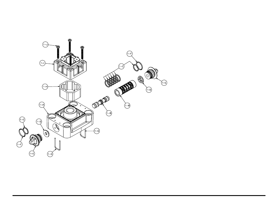
Air Distribution Valve Assembly Drawing
MAIN AIR VALVE ASSEMBLY PARTS LIST
Item
Part Number
Description
Qty
1
031-166-000
Air Valve Assembly
1
1-A
095-106-551
Body, Air Valve
1
1-B
031-132-000
Sleeve and Spool Set
1
1-C
560-101-360
O-Ring
8
1-D
132-036-357
Bumper
2
1-E
165-122-551
End Cap
2
1-F
560-026-360
O-Ring
2
1-G
675-062-115
End Cap Retainer
2
1-H
530-031-550
Muffler
1
1-I
165-109-551
Muffler Cap
1
1-J
710-011-115
Self-Tapping Screw
4
For Conductive Acetal pumps:
1
031-166-001
Air Valve Assembly
1
1-A
095-106-503
Body, Air Valve
1
1-E
165-122-503
Cap, End
2
1-I
165-109-503
Cap, Muffler
1
(Includes all other items used on 031-166-000 above)
For Pumps with Virgin PTFE coated hardware:
1
031-166-002
Air Valve Assembly
1
1-G
675-062-308
End Cap Retainer
2
1-J
710-011-308
Screws, Self-Tapping
4
(Includes all other items used on 031-166-000 above)
For pumps with alternate Mesh or Sound Dampening mufflers or Piped
Exhaust:
1
031-168-000
Air Valve Assembly
1
(Includes all items used on 031-166-000 above minus items 1-H, 1-I
and 1-J)