Connecting to the rs485 interface/baudrate, 3 wait time tw, 4 connection of additional analyzing devices – LumaSense Technologies IS 320 User Manual
Page 12: 2 mechanical installation, 1 sighting led targeting light, 3 wait time t, Pyrometer 1 e.g. address, Sec)
IS 320 • IGA 320 Manual
General 12
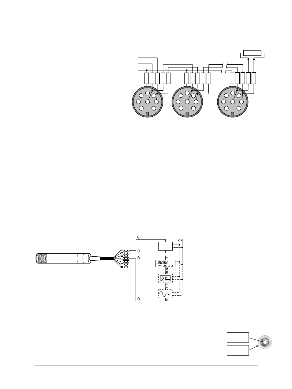
Connecting to the RS485 Interface/Baudrate
The pyrometer is operated in half-
duplex mode. To prevent reflections
due to long stubs, A1 and A2, as
well as B1 and B2, are bridged in
the 8-pin round connector of the
connecting cable. This also
safeguards against the interruption
of the RS485 bus system should a
connecting plug be pulled out. The
master labels mark the connections
on the RS485 converter.
The transmission rate of the serial
interface in Baud (Bd) is dependent
on the length of the cable. Values
between 1200 and 38400 Bd may be
set using the InfraWin software (see Chapter 5) or the command “br” when using other
communication software (see the command table in Chapter 8, Data Format UPP). The baud rate
is reduced by 50% when the transmission distance is doubled. Typical cable length for 19200 Bd is
2 km.
3.1.3 Wait Time t
w
In the case of a slow RS485 connection, it is possible that the connection will not be fast enough
to receive the pyrometer’s answer to an instruction of the master. In this case, a wait time
(between 00 and 99 bit) can be set to slow down the data transfer (e.g.: t
w
= 02 at a baud rate
9600 means a wait time of
2
/
9600
sec).
3.1.4 Connection of Additional Analyzing Devices
Additional analyzing instruments, such as an LED digital display instrument, only need to be
connected to a power supply and the analog outputs from the pyrometer. Other instruments,
such as a controller or printer, can be connected to the display in series as shown below (total
load of resistance max. 500 Ohm).
3.2 Mechanical Installation
3.2.1 Sighting LED Targeting Light
The pyrometer is equipped with a red LED targeting light to facilitate
positioning with the object to be measured. At the optimal distance, this light
shows its smallest diameter and a sharp image. At other distances the point
yellow
LED digital display
Controller
Power supply
green
brown
white
230V ~
24 V DC
°C
Writer
2
3
4
5
1
7
6
8
2
3
4
5
1
7
6
8
2
3
4
5
1
7
6
8
A
B
B
1
A
2
B
2
A
1
B
1
A
2
B
2
A
1
A
2
B
2
A
1
B
1
Master
Pyrometer 1
e.g. address
00
Pyrometer 2
e.g. address 01
Pyrometer 32
e.g. address 31
S
G
R
N
D
G
R
N
D
G
R
N
D
LED point
in focus
Reflector
shadow
Terminator
120 Ohm