Installation – Lincoln Electric IM840 ETHERNET_DEVICENET MODULE K2436-1 User Manual
Page 14
A-7
INSTALLATION
ETHERNET / DEVICENET MODULE (COMMUNICATION INTERFACE MOUNTING)
A-7
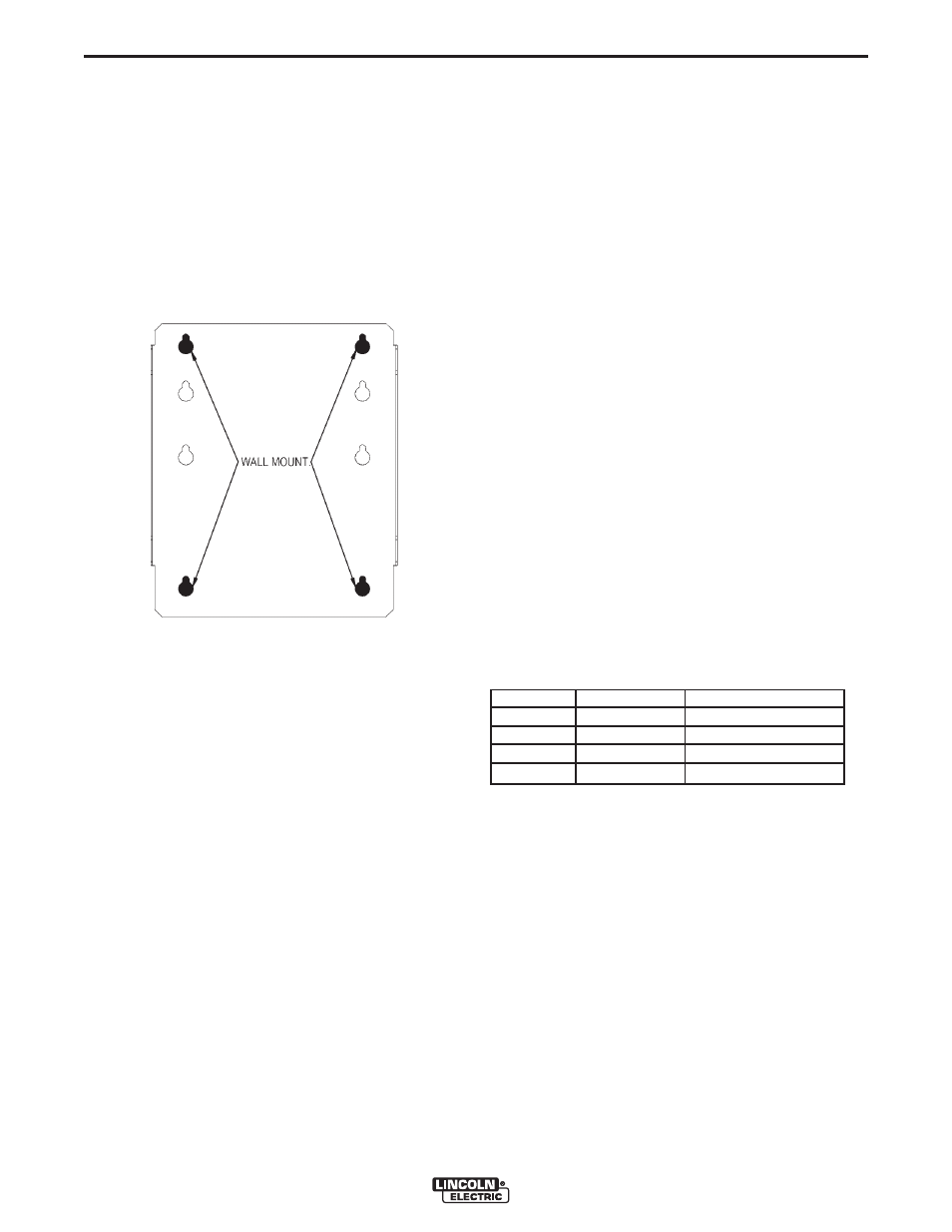
WALL MOUNTING
1. Turn OFF input power to the power source.
2. Drill and tap holes into the fixture or utilize wall
anchors that align with the top two and the bottom
two keyholes of the Mounting Bracket that is includ-
ed with the Communication Interface (see Figure
A-7). It is suggested that at least four 1/4”-20 fas-
teners be used to mount the Communication
Interface. Through holes may be drilled if nut and
bolt combinations are to be used.
FIGURE A-7
3. Start the fasteners into the drilled and tapped
mounting holes leaving enough space between the
heads of the screws and the mounting surface to
clear the Mounting Bracket sheet metal thickness.
4. Place the mounting bracket included with the
Communication Interface over the loosened
screws.
5. Pull the bracket down to engage the keyhole slots
with the fasteners.
6. Tighten the fasteners to secure the Mounting
Bracket.
7. Place the Communication Interface onto the
Mounting Bracket by lining up the slots along the
bottom with the tabs on the Bracket. The
Communication Interface should be oriented such
that the cable connectors face down.
8. Pull down on the Communication Interface to "lock"
the tabs into the slots.
9. At this point, the holes on the sides of the
Communication Interface should align with the
holes in the tabs of the Mounting Bracket.
10. Place the self-tapping screws included with the
Communication Interface into the holes on the
sides of the Interface and the Bracket and tighten
to secure the assembly.
11. Attach the 5-pin Control Cable included with the
Communication Interface to the mating ArcLink
(IN) cable connector on the bottom of the
Interface. The connector to be used on the
Interface is the one with the threaded collar
attached to the cable connector.
12. Connect the other end of the Control Cable to the
mating receptacle on the power source.
13. The Communication Interface mounting is com-
plete.
BOARD SETUP
DeviceNet Baud rate: The default Baud rate is 125K.
If another Baud rate is desired, reference table 1 in
and set switches 1 and 2 of bank S2. Every device on
a DeviceNet network must have the same Baud Rate.
The Dip Switches can be accessed by removing the
cover.
DeviceNet Baud Rate (Table 1)
Switch 1
Switch 2
Baud Rate
Off
Off
125K
On
Off
250K
Off
On
500K
On
On
Programmable Value
DeviceNet MAC ID: The default MAC ID is 62. Every
device on the DeviceNet network should have a
unique ID. If another MAC ID is desired, refer to Table
3 of this quick start guide/ to set switches 3 through 8
of bank S2.
COMPLETE BOARD INSTALLATION
• Replace cover being careful to avoid cutting or
pinching any wires.
• Reinstall the screws in cover.
• Re-apply power and verify the appropriate status
lights on the Power Source and Communication
Interface are green.