Installation – Lincoln Electric IM840 ETHERNET_DEVICENET MODULE K2436-1 User Manual
Page 13
A-6
INSTALLATION
ETHERNET / DEVICENET MODULE (COMMUNICATION INTERFACE MOUNTING)
A-6
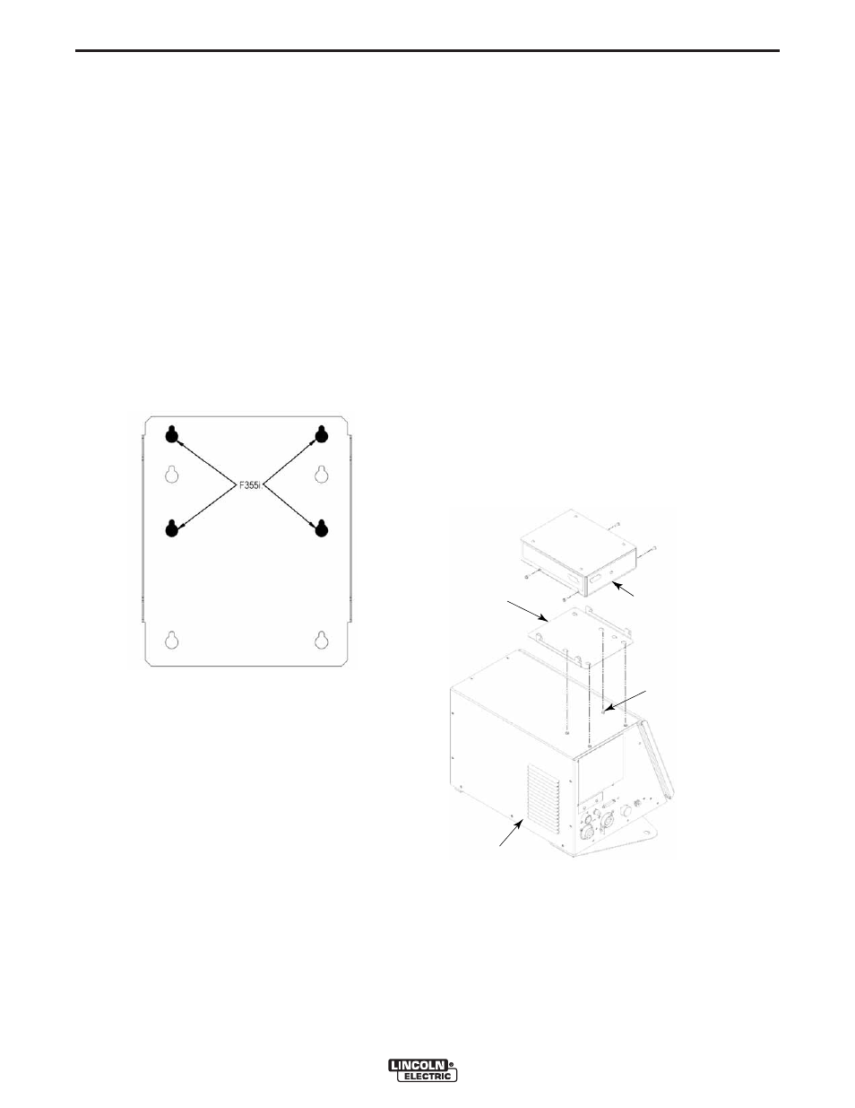
MOUNTING COMMUNICATION INTER-
FACE TO THE POWER WAVE F355i
(See Figure A-6)
1. Turn OFF input power to the F355i.
2. Loosen the 4 wraparound screws on the top, left of
the F355i. BE CAREFUL NOT TO REMOVE THE
SCREWS – THE DIVIDER PANEL INSIDE THE
F355i MAY SHIFT, CAUSING DIFFICULTY IN
REPLACING THE SCREWS.
3. Place the mounting bracket included with the
Communication Interface over the loosened screws
on top of the F355i. The top two keyholes and the
middle two keyholes in the bracket should align with
the screws in the wraparound (see Figure A-5).
FIGURE A-5
4. Pull the bracket toward the right of the F355i to
engage the keyhole slots with the screws.
5. Retighten the screws to secure the Mounting
Bracket.
6. Place the Communication Interface onto the
Mounting Bracket by lining up the slots along the
bottom with the tabs on the Bracket. The
Communication Interface should be oriented such
that the cable connectors face toward the right of
the F355i.
7. Pull back on the Communication Interface to "lock"
the tabs into the slots.
8. At this point, the holes on the sides of the
Communication Interface should align with the
holes in the tabs of the Mounting Bracket.
9. Place the self-tapping screws included with the
Communication Interface into the holes on the
sides of the Interface and the Bracket and tighten to
secure the assembly.
10. Attach the 5-pin Control Cable included with the
Communication Interface to the mating ArcLink
(IN) cable connector on the back of the Interface.
The connector to be used on the Interface is the
one with the threaded collar attached to the cable
connector.
11. Route the Control Cable along the top of the F355i
toward the left side and connect the Control Cable
to the mating receptacle on the left side of the
F355i.
12. The Communication Interface mounting is com-
plete.
13. See BOARD SETUP at the end of this Installation
Section.
FIGURE A-6
COMMUNICATION
INTERFACE
MOUNTING
BRACKET
4 WRAPAROUND
SCREWS (LOOSEN DO
NOT REMOVE SCREWS)
F355i