Powertrak, Light control plus switch installation (continued), For 4, 5,or 6 foot powertrak machines only – Hired-Hand PowerTrak: LIGHT CONTROL PLUS SWITCH INSTALLATION User Manual
Page 2
POWERTRAK
LIGHT CONTROL PLUS SWITCH INSTALLATION (Continued)
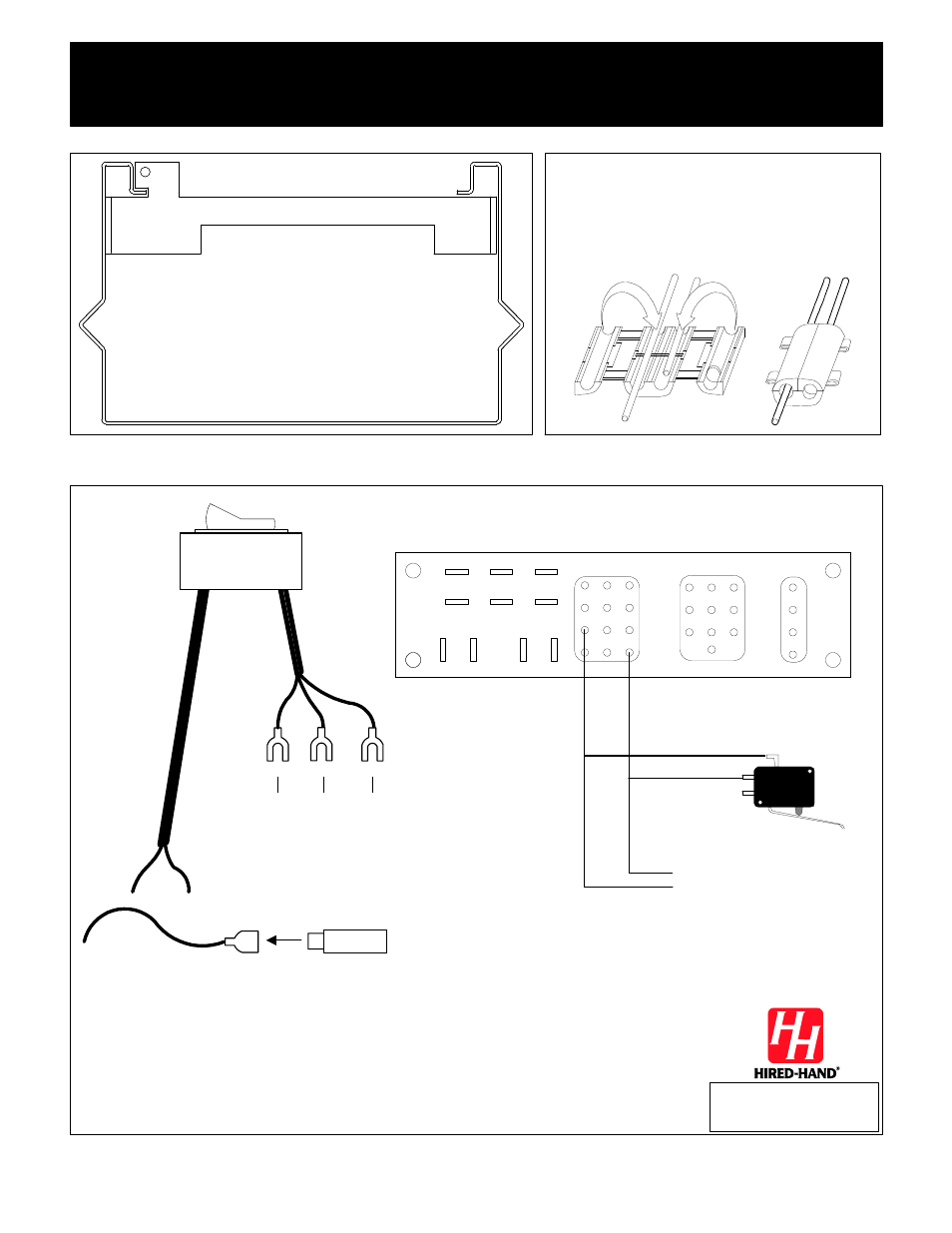
For 4, 5,or 6 foot PowerTrak machines only:
Replace the brace across the center front of the
machine. This brace is held in place by four bolts.
Use the original bolts to install the new brace.
Connect the wires from the switch to the wires
from the limit switch harness at the bottom of the
machine.
Use the connectors as shown below, to splice
the end of the new wire to any part of the existing
wire. Match pink and tan wires color to color.
All wiring must be performed in
accordance with all National and Local
Electric Codes. Installation by qualified
electrician recommended.
Red
Black
White
10
11
12
Connect to these positions on
Light Control Plus Controller
Red
Black
J15
J14
J13
Black
White
Shield
J9
J10
J11
J5
J4
J6
J7
P/N 3580-0135
Motor
Controller
Limit Switches
Low
er
Upper
Fan
Switch
5 August 1994 T.E.
PCB135 (Rev A)
Circuit board in Power Trak
Pink
Tan
To Limit
Switches
Pink
Tan
Disconnect black wire on PowerTrak limit switch harness.
Connect this black wire to the red wire from the rocker switch
above.
1.
2.
Connect the black wire from the rocker switch to the place on the
PowerTrak you removed the wire from in step 1. The rocker switch
is now connected in series.
3.
1.
2.
3.
Black wire on
PowerTrak
Limit Switch on
PowerTrak
HIRED-HAND, INC.
· 1733 Co Rd 68 · Bremen, AL 35033 · Phone 1-800-642-0123 · Fax 205-287-2000
PowerTrak Light Control Plus Switch Installation
4801-0138 Rev 7/00
PowerTrak's manufactured before 4/7/97 Serial No's 28809 and lower.