Hired-Hand PowerTrak: LIGHT CONTROL PLUS SWITCH INSTALLATION User Manual
Powertrak, Light control plus switch installation, Purpose of equipment
POWERTRAK
LIGHT CONTROL PLUS SWITCH INSTALLATION
HIRED-HAND, INC.
· 1733 Co Rd 68 · Bremen, AL 35033 · Phone 1-800-642-0123 · Fax 205-287-2000
PowerTrak Light Control Plus Switch Installation
4801-0138 Rev 7/00
Purpose of Equipment:
To give a signal to turn on or off
equipment when curtain height reaches
the position you set.
Warning!
Disconnect all power sources to PowerTrak before
attempting to install the Auxiliary Switch. Electric Shock
may result.
Tools Required:
Drill with 1/4" and 3/16" bit
3/4" Wrench
1/4" Allen Wrench
Pliers
To Set Switch Position:
Manually raise or lower curtains to desired height.
Place template over front of PowerTrak, with the black
tape facing the right side. Drill the four holes in the side
of the PowerTrak as shown by the template.
Follow Installation instructions.
When installation is complete, manually raise and lower
curtain past the switch slowly to be sure that the
switches operate without binding.
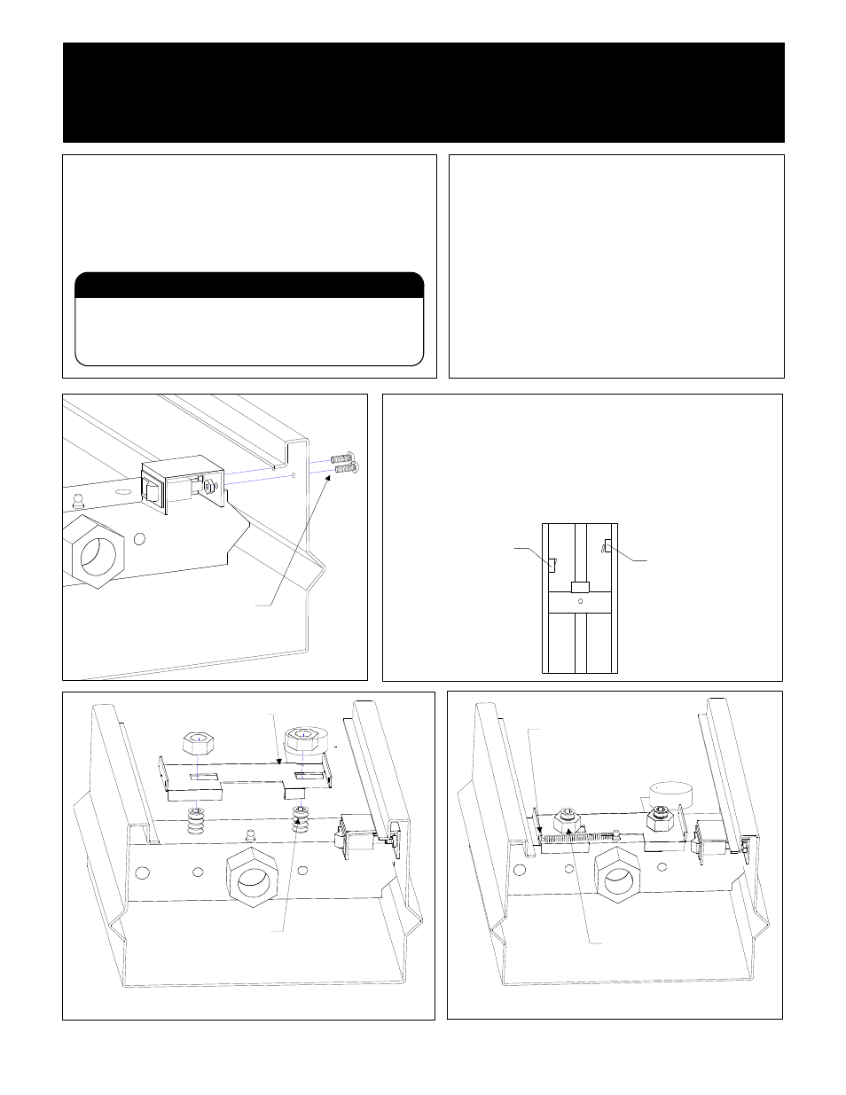
Attach switch and bracket using
the two nuts and bolts provided.
Top of Machine
Move curtain to desired height before
drilling holes for switches!
When installing the switches, be sure to install the
rocker switch on your left side, facing machine. Install
the limit switch on the right-hand side of the machine.
Limit Switch
(Bend in arm should
be even with center of
rocker switch
Rocker Switch
Replace existing setscrews
with new longer setscrews.
Place bracket on new setscrews*, and
secure with nuts. Be sure the bracket
can slide from side to side.
Top of Machine
* Note: For Serial Numbers 20825 and higher(DOM 3/4/96), you must add two 1/2 inch washers to
the setscrews between bracket and load nut.
Attach one end of tensioning
spring to bracket as shown,
and the other end around the
grease fitting.
Note: Nuts should not be
completely tightened so
that the bracket may slide
back and forth freely.
Top of Machine