Physical description/drawing – Hired-Hand PowerTrak User Manual
Page 4
Part No. 4801-0154 Rev 8-07
PowerTrak
Page 4 of 22
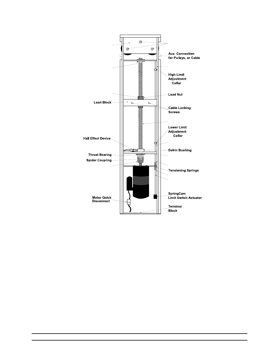
4. Physical
Description/Drawing
Limit Switch Assembly
The Limit Switch Assembly includes the limit switches, tensioning springs, guide rod, cotter pins, and
adjustment collars. These components work together to stop the motor when the machine reaches the end of
its travel. The auxiliary switches allow you to hook up equipment that should run/not run when the curtains
are closed, or all the way open.
Drive Assembly
The drive assembly includes the Motor, bearings, coupling, screw, and the load block. The PowerTrak motor
you have depends upon the speed of the machine you ordered. You may have a 15, 30, or 60 RPM motor.
Pulley Assembly
The pulley assembly is at the top of the machine. It consists of three pulleys which are spaced to allow the
cables to go out both sides of the machine for two curtain operation, or you can run both cables out of the
same side for one curtain operation. NOTE: An optional chain and sprocket assembly is also available
which can be used instead of the pulley assembly.
Wiring Harness
The wiring harness includes all connectors, and wiring to route power through the limit switches, and to the
motor. See wiring diagram in the back of this manual for detailed wiring instructions.
Pully
Assembl
Upper
Bearin
Cotter
Cotter
Cotter
Cotter
Grease
Grease
Grease
Drive
Guide
Lovejoy Coupling