Warning, Maintenance, Wiring diagrams, schematics, etc – Hired-Hand Farm Hand Series: Stage Master User Manual
Page 19
Part No. 4801-0151 Rev 4-06
Farm Hand Stage Master
19 of 40
Brief Description of Progressive Cool Timer Option
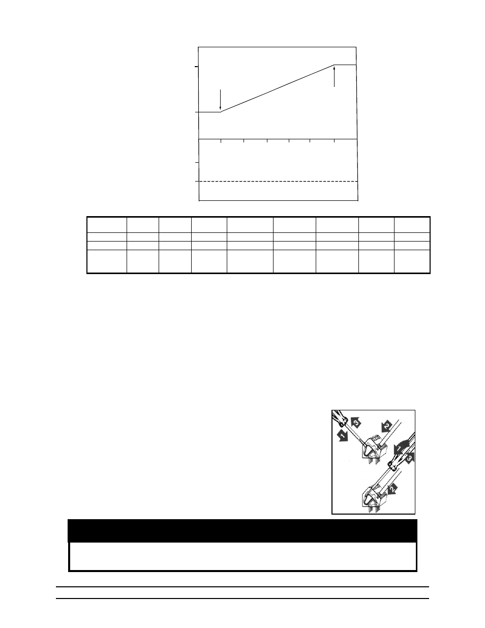
As you can see from graph 3, as the temperature increases above the Minimum OnPoint,
(OFF=75ºF) the Runtime % progressively increases until it reaches 100% at its Maximum OnPoint
(ON = 80ºF). When using this option, it is not necessary to set P10 or P11 for the stage. These
parameters only apply to variable speed operation.
10. Maintenance
Check the calibration of your sensors at least once per quarter. To do this, you will need to have two
persons: one at the sensor with a trusted thermometer, and one at the controller to set the sensor to the
proper setting.
11. Wiring Diagrams, Schematics, etc.
All wiring connections for stages, curtain machines, variable speed
fans, and curtain sensors inside the controller are made without
terminals on the end of the wire. To make the connection, strip about
¼” of the insulation off the wire, and follow the diagram below.
1. Insert a small screwdriver into either the hole shown in the
diagram.
2. Insert the stripped end of the wire into the hole shown in the
diagram.
3. Remove the screwdriver, and tug slightly on the wire to check
that it is snug.
Warning!
Do not connect more than 12 amps of load to any one stage. The Variable Speed
Circuit will carry up to 12 amps.
100
Percent Of R
unti
m
e
Percent Of
Full S
pee
d
50
50
100
76
78
80
77
75
79
Graph 3 Progressive Cool Timer Option
Maximum
OnPoint
TEMPERATURE (F)
Minimum
OnPoint
Table 3 Progressive Cool Timer Option
Setting Stage
Sensor
Stage
Mode
Stage
Timer
Minimum
OnPoint
Maximum
OnPoint
Minimum
Runtime %
Motor
Curve
Var/
Timer %
Parameter
P1 P2 P3 OFF
ON
P10
P11 N/A
Value
10 02 02 75
80
N/A N/A 50
Option
Sensor 1
Cool Stir
Timer ON
Stage begins
varying
Runtime
Stage runs
continuously
N/A
N/A
Refer to
Section
5.1