2 progressive cool timer option – Hired-Hand Farm Hand Series: Stage Master User Manual
Page 18
Part No. 4801-0151 Rev 4-06
Farm Hand Stage Master
18 of 40
Pct." parameter as described in Section 5.1. In this example, Var/Timer Pct. is set to 50%. The Minimum
Runtime percentage is set to 40% (P10=40).
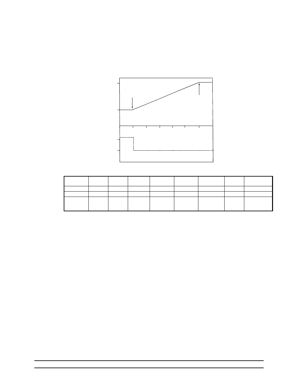
Below 75ºF, a fan connected to the variable speed stage will run at 50% speed for 40% of the system timer
(either 2 minutes for a 5 minute timer, or 4 minutes for a 10 minute timer). When the temperature reaches
75ºF, the fan will run at minimum speed (50%) continuously. As the temperature increases, the fan speed
progressively increases from 50% up to 100% at 80ºF. Above 80ºF, the fan runs continuously at its
maximum speed.
Table 2 Example Of Variable Speed Fan Control
Brief Description Of Variable Speed Fan Control
From the graph, you can see that at 78
°F, the variable speed fan will run at 70% of maximum
speed. Below 75
°F the variable speed fan will run at it’s minimum speed, for the minimum timer
percentage (P10). Above 80
°F the variable speed fan will run at 100% continuously.
9.5.2 Progressive Cool Timer Option
The progressive Cool Timer operation varies the Runtime percentage while keeping the fan speed
constant. Refer to Graph 3 and Table 3. The stage timer is set to ON (P3=2). In this case, the
stage timer setting is P3=2 to indicate progressive cool timer operation.
As in the previous example, the Maximum OnPoint is set to 80ºF (ON=80), and the Minimum
OnPoint is set to 75ºF (OFF=75). The Runtime percentage is progressively varied over this
temperature range from 75º to 80º. The "Var/Timer Pct." parameter, which in this case refers to
the stage's minimum runtime percentage, is set to 50 (See Section 5.1)
At 75ºF and below, the stage will operate at full speed on a system timer running at its minimum
runtime percentage (Var/Timer Pct. = 50). As the temperature increases above 75ºF so does the
stage's runtime percentage. Once the temperature rises above 80ºF, the stage will run
continuously.
Pe
rce
nt
Of Runti
m
e
Pe
rc
en
t Of
Fu
ll S
pe
ed
100
50
50
100
76
78
80
77
75
79
TEMPERATURE (F)
Graph 2 Variable Speed Fan
Minimum OnPoint
Minimum Speed
Maximum OnPoint
Maximum Speed
Setting Stage
Sensor
Stage
Mode
Stage
Timer
Minimum
OnPoint
Maximum
OnPoint
Minimum
Runtime %
Motor
Curve
Var/Timer
Percentage
Parameter
P1 P2 P3 OFF ON P10
P11
N/A
Value
10 02 00 75
80
40
0 50
Option
Sensor 1
Cool Stir
No Timer
Fan begins
Varying
Speed
Fan begins
Maximum
Speed
Runtime
40%
Standard
single
phase
Refer to
Section 5.1