Connecting ac power to the controller, See details below – Hired-Hand Farm Hand Series: POWER VENT INLET User Manual
Page 15
Part No. 4801-0149 Rev 1-01
Farm Hand Power Vent
13
11.5.
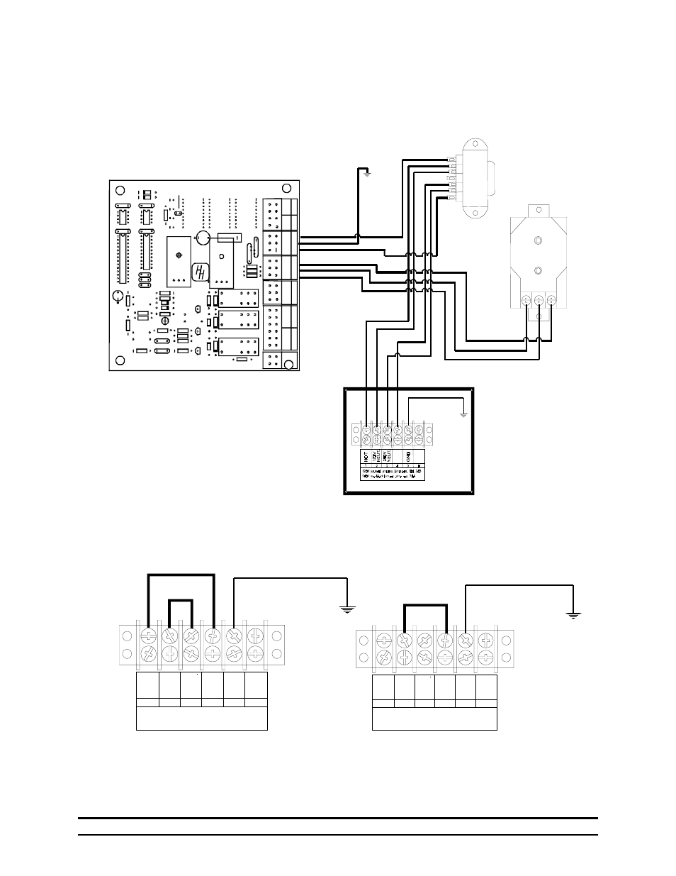
Connecting AC Power To the Controller
This diagram applies to Standard units without pre-installed cord sets.
W
6
R101
R
HIRED-HAND
Com
N.O.
N.C.
Al
ar
m
R100
Q100
Z100
D100
Z3
D2
RLY2
RLY100
R16
R15
R14
W
5
R4
C1
TER1
P1
BP4
BP3
BP2
BP1
Open
Close
Close
Com
Open
Com
Un
it
2
Un
it
1
Signal
GND
+12V
Gnd
~
~
W
hite
Black
-
+
Da
ta
Te
m
p
A
C-
IN
Xd
uc
er
MOV1
M
O
V2
R1
C3
C2
X1
U1
U2
U4
U3
R8
Z5
Z6
Q1
Q2
C4
BR1
R10
R12
R13
R11
R7
C5
R3
C6
D1
Z4
RLY1
VR2
OUT IN
ADJ
RKS-11DX-12
Network
Term
ination
PCB146 Rev 'C'
Copyright (c) 1997, '98
Hired-Hand Mfg, Inc
Ellard
ADJ
IN
OUT
VR1
R9
Z1
Z2
R5
W
1
W
2
W
3
W
4
Curtain
Closed
R300
Note: You must install jumper wires on the AC inputs as shown in the drawings below.
120V use red jumpers, jump pos. 1&4, 2&3
240V use black jumper, jump pos. 2&4
HO
T
12
0V
NE
U
T
24
0V
NE
U
T
GN
D
1
2
3
4
5
6
120V use red jumpers, jump pos. 1&4, 2&3
240V use black jumper, jump pos. 2&4
HO
T
12
0V
NE
U
T
24
0V
NE
U
T
GN
D
1
2
3
4
5
6
120V 240V
See details below.
- Polar Cool: Portable Evaporative Cooling System (22 pages)
- Polar Cool: External Control Box (4 pages)
- Polar Cool: Pump & Float Replacement (2 pages)
- Polar Cool: PUMP REPLACEMENT (4 pages)
- Polar Cool: Wall Mount Kit (4 pages)
- Unitized Mega Cool (68 pages)
- Unitized Mega Cool: Square Bottom (63 pages)
- Mega-Cool: Square Reservoir (24 pages)
- Mega-Cool rev 6-09 (46 pages)
- Mega-Cool: Mega-Cool Pad Extender Kit (5 pages)
- Mega-Cool: Float Valve Replacement (1 page)
- Mega-Cool: Float Valve (Topaz) Replacement (1 page)
- Mega-Cool: In-Line Pump Motor Replacement (2 pages)
- Var-O-Matic (2 pages)
- System 1000 Power Vent (13 pages)
- System 1000 Power Vent (31 pages)
- System 500 Programs (Conventional Model) (5 pages)
- System 100 Variable Speed Controller (7 pages)
- System 500 Programs (Tunnel Model) (7 pages)
- System 1000 Power Curtain (17 pages)
- System 2000 AUTO TEMP (10 pages)
- System 2001 Power Curtain Controller (43 pages)
- System 500 Power Curtain Controller (31 pages)
- System 1000 Power Curtain Eight Stage Controller (34 pages)
- ICS-500 Environmental Controller (34 pages)
- Pressure Transducer Changeout (1 page)
- HH Software: HH.Net Router/Repeater (8 pages)
- HH Software: 900SS Wireless Network (10 pages)
- HH Software: Farm Manager (22 pages)
- HH Software: Data Shuttle Launch Pad (25 pages)
- Sens-O-Matic (Feed Hopper Switch) (2 pages)
- Manual Light Dimmer (2 pages)
- Electro Mechanical Controls (Relay-Switches): PHOTOHELIC POWER VENT (10 pages)
- Electro Mechanical Controls (Relay-Switches): PT Controller (9 pages)
- Electro Mechanical Controls (Relay-Switches): PC-DB Curtain Controller with DIF (6 pages)
- Electro Mechanical Controls (Relay-Switches): PC-DB Curtain Controller with Timer Override (7 pages)
- Electro Mechanical Controls (Relay-Switches): Photohelic Gauge (1 page)
- Feed Management System (15 pages)
- Contactor Control System (CCS): 4, 8, or 12 Stage (19 pages)
- Contactor Control System (CCS): Triple Pole 16-Stage (7 pages)
- Contactor Control System (CCS): Vent Machine Override 3 Wire PowerTrak (1 page)
- Evolution 4000 Control System (86 pages)
- Evolution Series 1200: Variable Output With Override Pot (14 pages)
- Evolution Series 1200: Variable Output (12 pages)
- Evolution Series 1200 (64 pages)