Hired-Hand Evolution Series 3000/3001: Light Control Relay Assembly User Manual
Light control relay assembly, Description, 0 light control relay assembly installation
Light Control Relay Assembly
For EV-1200, EV-3000, & EV-3001 Controls
HIRED-HAND, INC.
• 1733 County Road 68 • Bremen, AL 35033 USA • Phone 256-287-1000 • Fax 256-287-2000
Manual Part No. 4802-5109 rev 2-07 Page
1 of 6
WARNING!
Only qualified electrician personnel familiar with the
construction and operation of this equipment and the
hazards involved should install and/or service this
equipment. Read and understand all instructions
and diagrams before proceeding. Failure to observe
this precaution could result in equipment damage,
severe bodily injury, or loss of life.
DESCRIPTION
The assembly described in this manual is used for
converting the EV-1200, EV-3000, or EV-3001
Variable Module connections into On/Off light control
contacts in cases when all other stages are being used
or will be used for other purposes. This assembly
provides a quick and simple relay assembly for
connecting to existing or new EV controllers. The
Light Control Relay Assembly includes the relay, one
prestripped red wire and one prestripped black wire to
connect to the Variable Module terminal block, and two
unterminated crimp terminals for connecting customer
supplied wires to the two normally open relay
terminals.
When the kit is received, check for shipping damage.
Part #
Description
Qty
1903-4044
HRNS EV1200 Light Contrl Relay
1
Small flat-head screwdriver
Crimping Tool
Wire Stripper
Section 1.0 - Light Control Relay Assembly Installation.
Section 2.0 - EV-1200 wiring diagrams.
Section 3.0 - EV-3000/3001 wiring diagrams.
Section 4.0 - EV-1200, EV-3000, or EV-3001
programming requirements.
1.0 Light Control Relay
Assembly Installation
A. Disconnect AC electrical power from all equipment.
B. Remove the 4-position black terminal block (Variable
Module) from the circuit board (EV-1200 PCB186
or EV-3000/3001 PCB169).
C. Connect the red wire to the ‘+’ and the black wire to
the ‘-‘ of either the VAR #1 side or the VAR #2
side. Tighten securely.
D. Place the 4-position terminal block back onto the
PCB Variable Module connection.
E. Remove the adhesive strip backing from the back
side of the Relay and place the relay
approximately midway between the enclosure
cover and PCB to allow access and removal of the
other terminal blocks
F. Ensure that all wires are clear from hole drilling
locations.
G. Refer
to
Section 2.0 or Section 3.0 for the wire
connections diagram from the Evolution controller
PCB to the Light Control Relay Assembly.
NOTE: All Stage Inputs must be jumpered as shown in
Section 2.0 or Section 3.0 wiring diagram.
H. Refer
to
Section 4.0 for Program Requirements.
WARNING!
Ensure that ALL Electrical Power Sources are
OFF during installation / wiring.
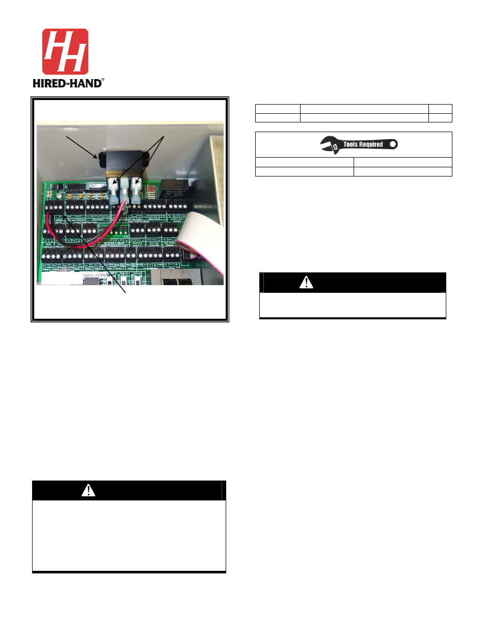
Figure 1: Light Control Relay Installed inside
EV-1200 Controller
Light Control Relay
Variable Module
Contacts
Connector
PCB168
PCB186
Crimp Terminals