Connection of power trak, Connection of rollseal tube motor, Rollseal tube motor – Hired-Hand Electro Mechanical Controls (Relay-Switches): PT Controller User Manual
Page 6
Part No. 4801-5042 Rev 9/99 PT Controller 4
1
2
3
4
5
6
7
8
9
10
11
12
13
14
15
OPEN
CLOSE
RED
BLACK
WHITE
GREEN
Hot
IN
Thermostat/Control
L1
Power Supply
L2
GND
OPEN
CLOSE
Hot
IN
UNIT 1
UNIT 2
(Open)
(Ground)
(Close)
(Common
)
POWER
SUPPLY
POWER
SUPPLY
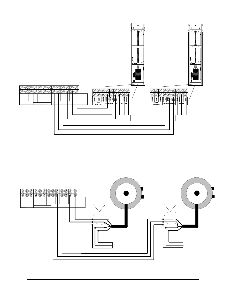
8. Connection of Power Trak
9. Connection of RollSeal Tube Motor
This diagram is for wiring RollSeal inlets to PT Controller.
This can be for control or interface with another controller.
1
2
3
4
5
6
7
8
9
10
11
12
13
14
15
OPEN
CLOSE
RED
BLACK
WHITE
GREEN
Hot
IN
Thermostat/Control
L1
Power Supply
L2
GND
OPEN
CLOSE
Hot
IN
UNIT 1
UNIT 2
(Open)
(Ground)
(Close)
(Common
)
RED
CLOSE
WHITE
GREEN
GROUND
NEUTRAL
HOT
110 VAC
POWER SUPPLY
HOT IN
OPEN
BLACK
Swap according to
direction needed for
opening
ROLLSEAL
TUBE
MOTOR
RED
CLOSE
WHITE
GREEN
GROUND
NEUTRAL
HOT
110 VAC
POWER SUPPLY
HOT IN
OPEN
BLACK
Swap according to
direction needed for
opening
ROLLSEAL
TUBE
MOTOR
Note:
Red and Black wires from motor are for direction,
connections made according to which is open or close.
Note:
Unit 1 connection is identical to unit 2 shown below.
To reverse the direction interchange the terminal
positions 9 &10 (unit 1) or 12 & 13 (unit 2).