Hired-Hand Light Traps: Installing Light Trap for Fan User Manual
Page 2
Hired-Hand Mfg., Inc. • 1733 Co Rd 68 • Bremen, Alabama 35033 • Phone 256-287-1000 • Fax 256-287-2000
Sheet Part No. 4801-5500 Rev. 12-05
Page 2 of 4
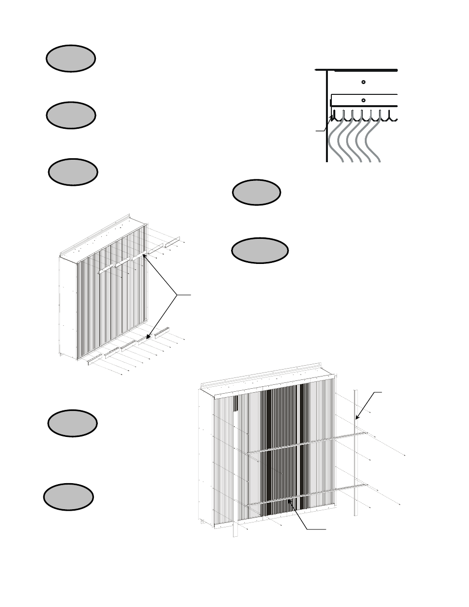
12" Extrusion
Spacers
STEP 5
With the front of the Light Trap facing upward,
install the Extrusions. See Figure 4. The two ribs of the
extrusion should face the left of the unit. Install Extrusions left
to right skipping the first notch spacers.
STEP 7
Attach the Left and Right
Trim using five 1004-0080 screws.
See Figure 6.
STEP 6
Attach the 12” Extrusion Spacers along
the Top and Bottom of the unit using two 1004-0080
screws per 12” Spacer. See Figure 5.
STEP 8
Attach the two Front
Extrusion Spacers to the unit using
four 1004-0080 tap screws per
Spacer. See Figure 6.
STEP 2
Attach the Top/Bottom Rear External Spacer
to the other Top and Bottom Panel using 1004-0080 tap
screws. See Figure 3.
STEP 3
Attach the Bottom Support Channel to the
Bottom Panel using 1004-0080 tap screws. See
Figure 3.
STEP 4
Attach the Back Extrusion
Spacer to the Sides using 1004-0080 tap
screws. See Figure 3.
Figure 5 - Fan Extrusion Spacers
Figure 6 – Install Left and Right Trim
Figure 4 – Install Extrusions
Skip first notch
Front Extrusion Spacers
Front Right
Trim