72 series, Vp-1 inverter, System programming - menu 1 – Ultra Start 72 Series User Manual
Page 24: Relay diagrams, Use spdt 12v relay, Door lock diagrams green, Page 24 install manual, Blue, Blue green
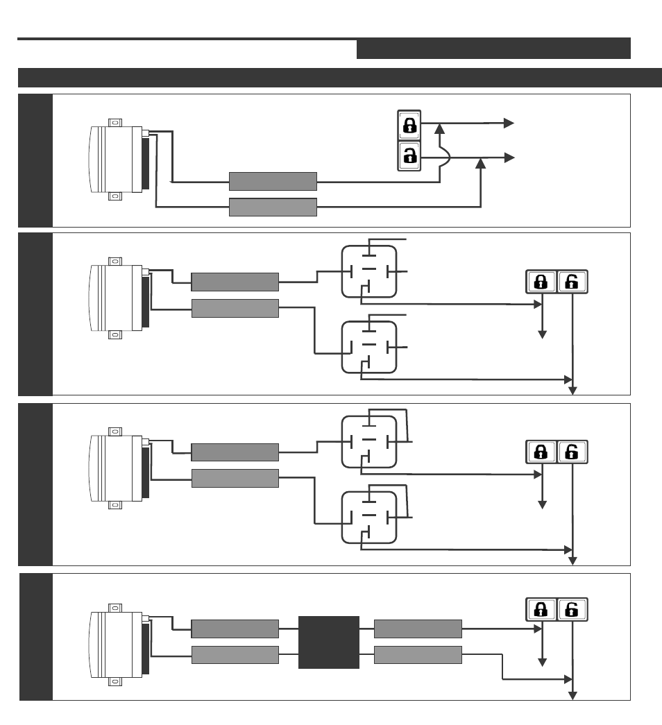
DOOR LOCK DIAGRAMS
Green
Vehicle's Lock/Unlock Switch
To Control
Relay or
Actuators
NEGATIVE DOOR LOCK
(LOW CURRENT)
Alarm and / or Starter
Module
Door lock Output
SYSTEM PROGRAMMING - Menu 1
PAGE 24
INSTALL MANUAL
RELAY DIAGRAMS
Vehicle's Lock/
Unlock Switch
USE SPDT 12v Relay
Blue
NEGATIVE DOOR LOCK
(LOW CURRENT)
Ground
Ground
12volts
12volts
87
86
85
87a
30
87
86
85
87a
30
Alarm and / or Starter
Module
Door lock Output
Blue
Green
Vehicle's Lock/
Unlock Switch
USE SPDT 12v Relay
POSITIVE DOOR LOCK
(LOW CURRENT)
12volts
12volts
87
86
85
87a
30
87
86
85
87a
30
Alarm and / or Starter
Module
Door lock Output
Blue
Green
POSITIVE TYPE USING
INVERTER
Alarm and / or Starter
Module
Door lock Output
Blue
Green
VP-1
INVERTER
Vehicle's Lock/ Unlock Switch
Blue
Green
72 SERIES