72 series, System programming - menu 1, System wiring details – Ultra Start 72 Series User Manual
Page 10: Page 10 install manual
SYSTEM PROGRAMMING - Menu 1
PAGE 10
INSTALL MANUAL
SYSTEM WIRING DETAILS
72 SERIES
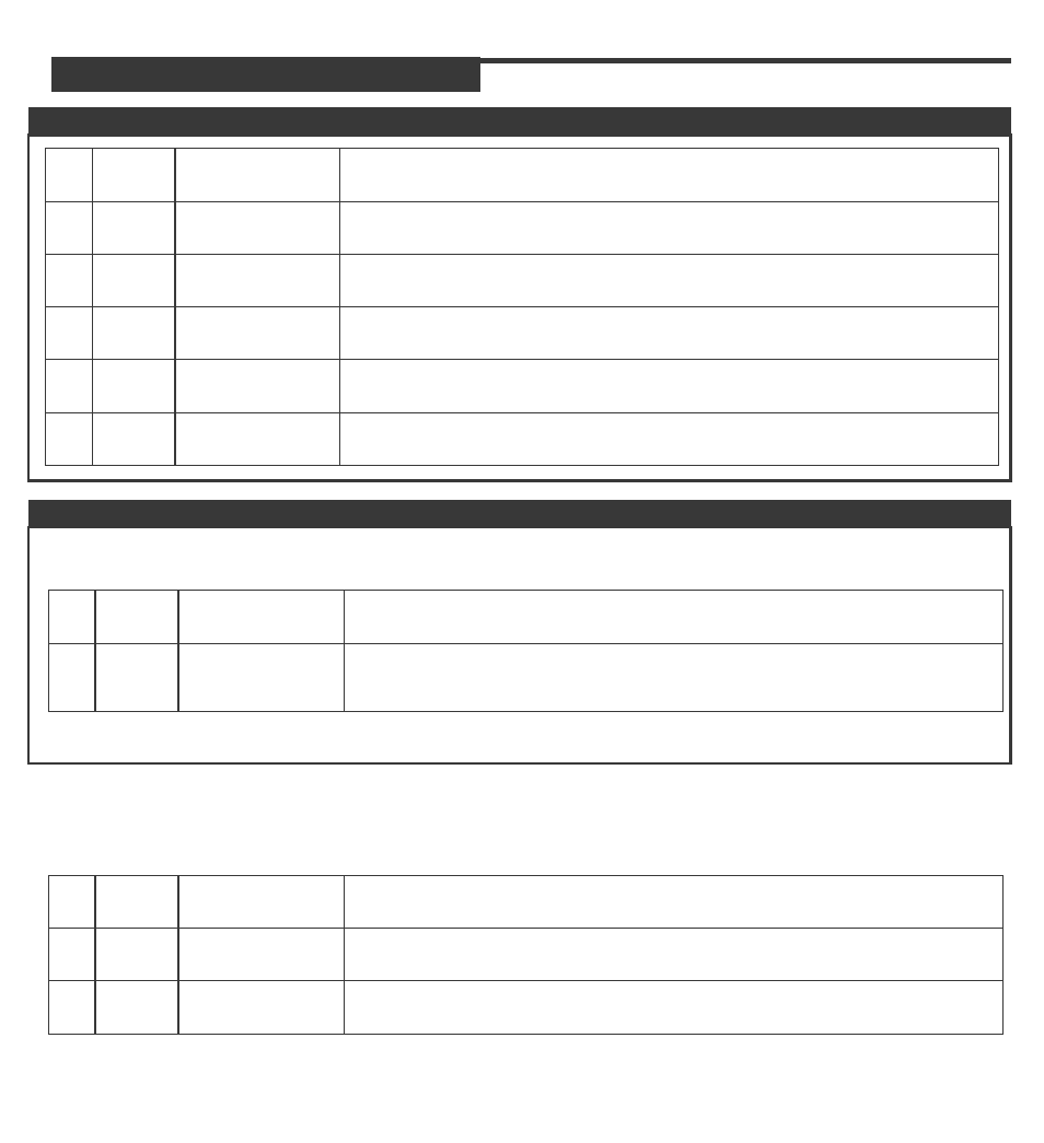
PIN 1
PIN 1
YELLOW
BLACK
PIN 2
PIN 2
GREEN
WHITE
PIN 3
RED
PIN 4
RED
PIN 5
BLUE
PIN 6
WHITE
STARTER
OUTPUT
SYSTEM
GROUND
This wire will test 0V with the key off, in the Accessory position and when the
Ignition is in the on. This wire is 12volts during the start/ crank position only.
Connect to chassis ground.
HEATER
OUTPUT
PARK LIGHT
OUTPUT
(SELECTABLE)
This wire will test 0V when key is off, 12volts in the ACC and IGN positions
and off during start/ crank position
Connect to the vehicles positive Park light wire or change the jumper and
connect to the vehicle negative Park light wire. The default position of the
jumper is Positive Park Light Output.
12v INPUT 30A This input supplies the 12volt power for the Accessory and Starter outputs.
12v INPUT 30A This input supplies the 12volt power for the Accessory and Starter outputs.
IGNITION
OUTPUT
This wire will test 0V in the off and Accessory positions the switch to12volts
in the Ignition and Start positions.
SELECTABLE
OUTPUT
2nd Ignition, Accessory or Start output. Programmable.
Note: This output does not switch to default when the system is reset.
PIN 1
GREEN
PIN 2
N / A
PIN 3
BLUE
(-) LOCK
OUTPUT
Connect to lock wire from the switch on vehicles with a negative type switch. **LOW
CURRENT ONLY**
12V + DOOR
LOCK INVERTER
This output will supply 12volts for a plug-in type door lock module. Do not use this input
to power-up relays **LOW CURRENT ONLY**
(-) UNLOCK
OUTPUT
Connect to unlock wire from the switch on vehicles with a negative type switch. **LOW
CURRENT ONLY**