Calibrator interface, Caution – Condec 3030 User Manual
Page 6
Caution
To avoid possible damage to calibrator or to
equipment under test:
• Use the proper jacks, function, and range for your measurement or
sourcing application.
2. Calibrator Interface
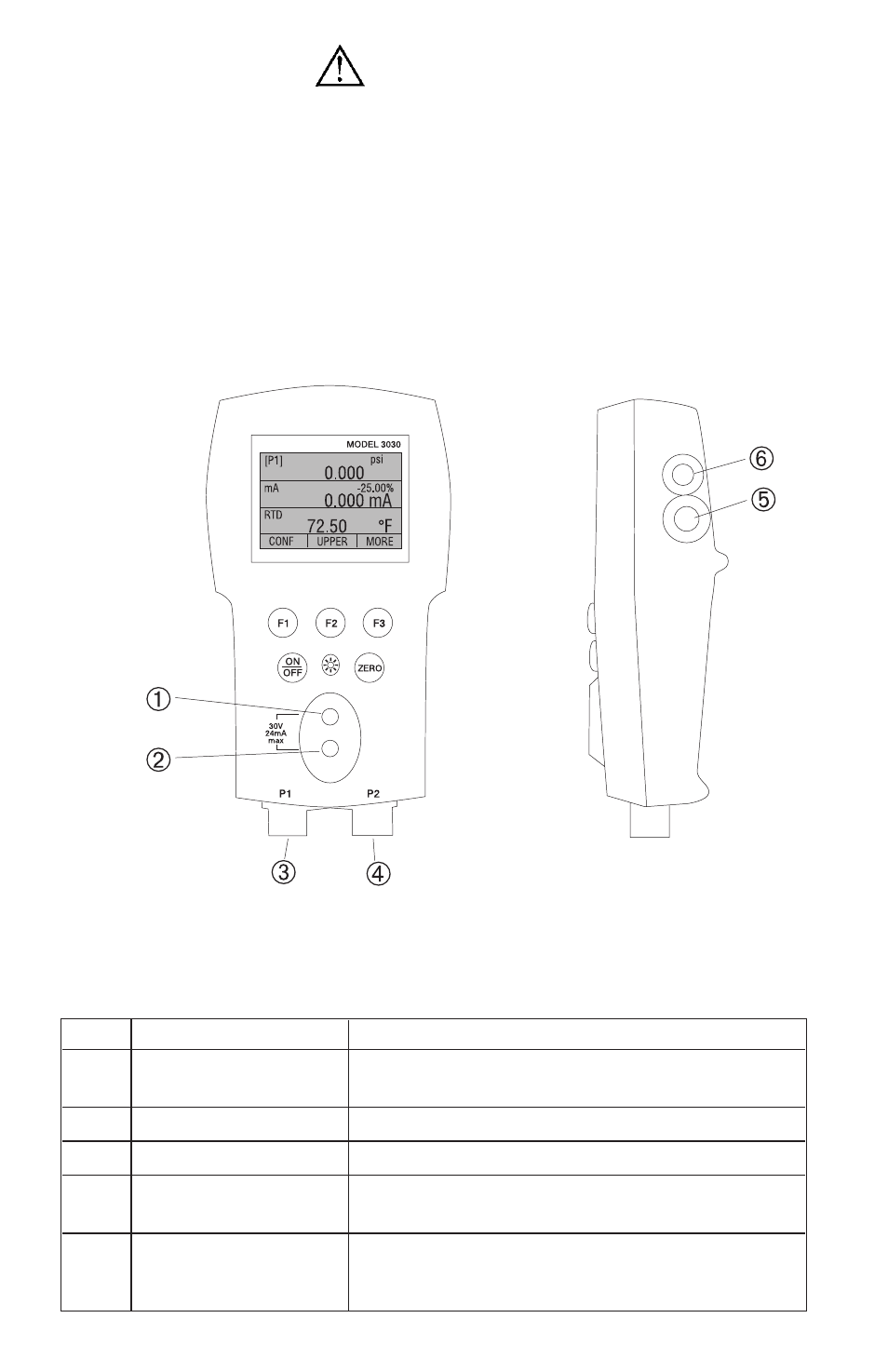
Figure 1 shows the location of the process measurement inputs,
while table 1 describes their use.
Figure 1 - Pressure Measurement Inputs
Table 1 Process Measurement Inputs
No. Name
Description
1, 2
Input Terminals
These terminal are used to measure current,
voltage and a contact closure for switch test.
3
P1 Pressure Port
This is the connection for the internal sensor P1
4
P2 Pressure Port
This is the connection for the internal sensor P2
5
RTD Probe Connector This connector is where the RTD probe is
plugged in.
6
Serial Interface
This is used to interface to optional external mod-
ules as well as for RS-232 serial communications
with a PC using the LEM-232 cable(optional).
4