6 geo, 2 are the amplifiers properly configured, 3 are the amps and the nx properly connected – Nexo GEO T User Manual
Page 48
Page 48/67
GEO
T
T
ANGENT
A
RRAY
S
YSTEM
C
HECK
L
IST
6 GEO
T
T
ANGENT
A
RRAY
S
YSTEM
C
HECK
L
IST
It is essential to execute all these check steps prior to perform a sound check on the “front end” to the
system. Following this checklist step by step will prevent many troubles and will save time in the end.
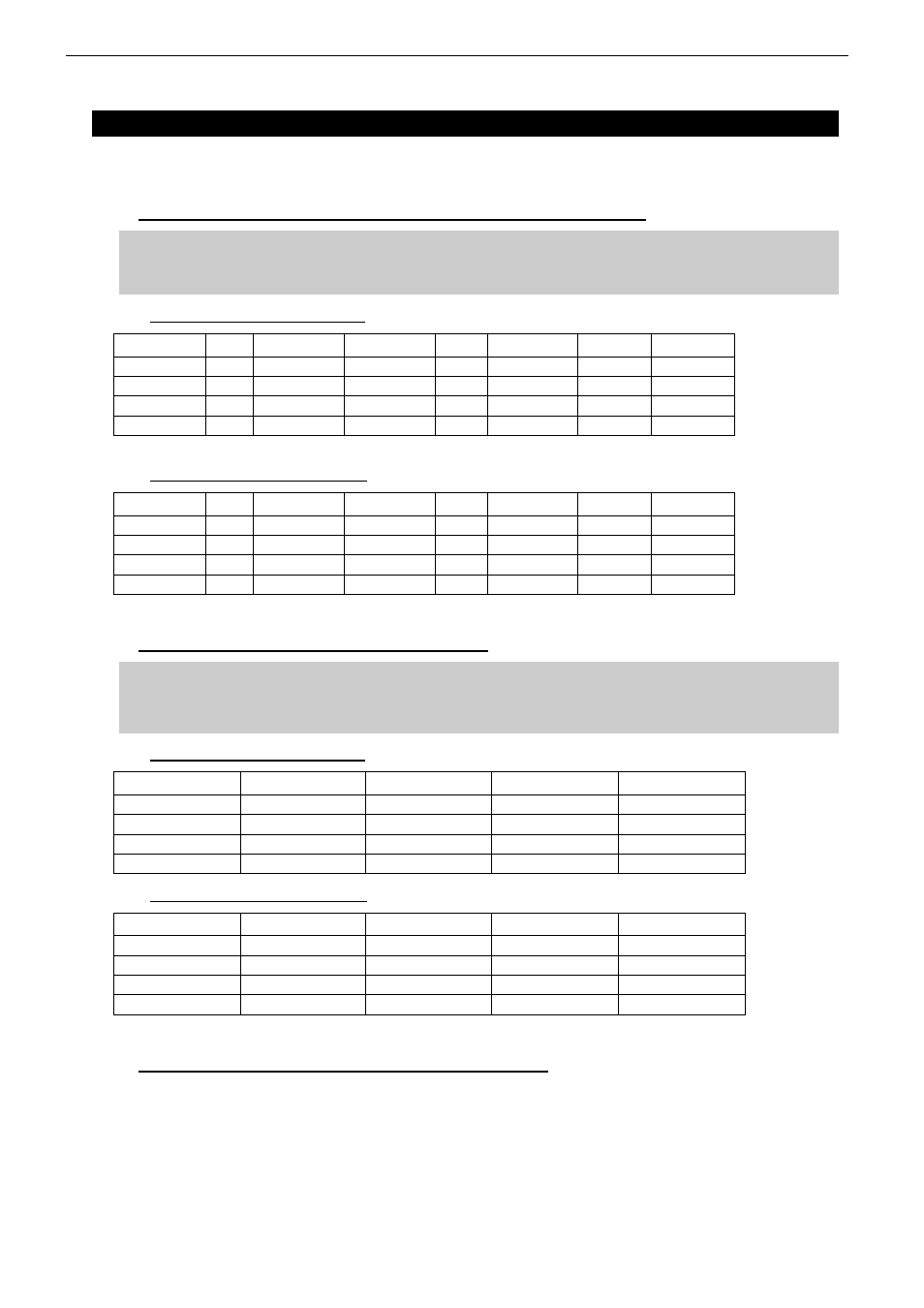
6.1 Are the NX242 Digital TDcontrollers properly configured?
IMPORTANT
If you must change any of the parameters listed above, make sure that you use the same
values on all NX242’s.
6.1.1 NX242 Load 2.13 and below
Freq. Band Gain Global Gain Amp Power Delay Sense Gain Array EQ Headroom
HF
32 dB
0 dB
1350 Watts
0 ms
0 dB
0 dB
5 bars
LF (rear)
32 dB
0 dB
2600 Watts
0 ms
0 dB
0 dB
5 bars
MF/LF (front)
32 dB
0 dB
2600 Watts
0 ms
0 dB
0 dB
5 bars
CD18 Sub
26 dB
0 dB
2000 Watts
0 ms
0 dB
0 dB
5 bars
6.1.2 NX242 Load 2.14 and above
Freq. Band Gain Global Gain Amp Power Delay Sense Gain Array EQ Headroom
HF
26 dB
0 dB
1350 Watts
0 ms
0 dB
0 dB
5 bars
LF (rear)
32 dB
0 dB
2600 Watts
0 ms
0 dB
0 dB
5 bars
MF/LF (front)
32 dB
0 dB
2600 Watts
0 ms
0 dB
0 dB
5 bars
CD18 Sub
26 dB
0 dB
2000 Watts
0 ms
0 dB
0 dB
5 bars
6.2 Are the amplifiers properly configured?
IMPORTANT NOTE FOR BRIDGE MONO MODE OPERATING AMPLIFIERS
• Bridged mono operating mode adds 6 dB voltage gain.
• Phase relation from amplifier input to output 1(+) and 2(+) has to be checked.
6.2.1 NX242 Load 2.13 and below
Freq. Band
Mode
Gain Switch
Limiter
High Pass
HF Stereo
32
dB
None
None
LF (rear)
Bridged Mono
26 dB*
None
None
MF/LF (front)
Bridged Mono
26 dB*
None
None
CD18 Sub
Stereo
26 dB
None
None
6.2.2 NX242 Load 2.14 and above
Freq. Band
Mode
Gain Switch
Limiter
High Pass
HF Stereo
26
dB
None
None
LF (rear)
Bridged Mono
26 dB*
None
None
MF/LF (front)
Bridged Mono
26 dB*
None
None
CD18 Sub
Stereo
26 dB
None
None
6.3 Are the amps and the NX properly connected?
Check that the sense LEDs on the NX242’s used for the full range Tangent Array Modules are
connected properly by applying a signal to the corresponding output and verifying that the correct
Sense LED illuminates.