Nexo GEO T User Manual
Page 36
Page 36/67
GEO
T
RIGGING PROCEDURE
4.5.3 First to second GEOT 4805
In “Compression Mode”, the linking bars must remain inside their respective cabinet side rigging plates.
Angles between one cabinet and the one below are adjusted using the upper cabinet “compression
mode setting” holes (see drawing below).
• Lift the bumper and top GEO T4805 assembly and position the next GEO T4805 below the
assembly.
• Lower the bumper and top GEO T4805 assembly carefully until the first and second GEO T4805
side rigging plates locate. Use front flanges and side vent ports to guide the assembly. The
rigging plates have been designed to locate against each other and so align the holes correctly.
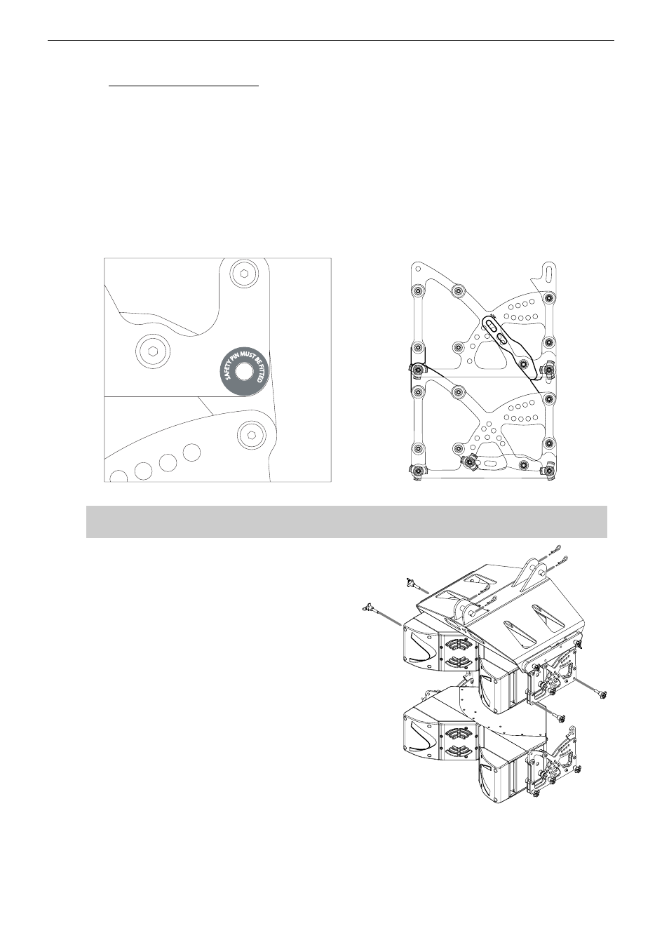
• Fix the two GEO T4805 by inserting one 12mm x 30 mm push-pin in the “SAFETY PIN MUST
BE FITTED” hole on each side (see figure below).
“SAFETY PIN MUST BE FITTED“ HOLE
GEO T4805: RIGGING PLATES IN COMPRESSION MODE
IMPORTANT
The push-pins for “SAFETY PIN MUST BE FITTED” holes must always be inserted first.
• Insert two additional 12mm x 30mm push-
pins in the front holes (see figure below).
• Lift the bumper and two first GEO T4805
to a height that allows convenient access
to the linking bars and the angle setting
holes.
• Release the linking bar push-pin from its
storage position (typically 0.125° when
stored in flight cases), rotate the linking bar
within the side rigging plate and position
the linking bar oblong hole in front of the
required angle value hole and insert the
push-pin.
• Repeat the angle setting procedure on the
opposite side of the cabinet.
• Check that all push-pins are locked and
that angle settings are identical on each
side.
FIRST GEO T4805 TO SECOND GEO T4805 ASSEMBLY