Stuart Turner Techflo Turbo 15TNH User Manual
Page 12
- 12 -
Cont ...
4.23
Supply Cord Replacement:
The supply cord and internal wiring within the terminal box are
routed and secured to ensure compliance with the electrical
standard EN 60335-1. It is essential that prior to any disturbance
of this internal wiring, all cable routing and securing details are
carefully noted to ensure re-assembly to the same factory pattern
is always maintained.
If the supply cord is to be changed or is damaged, it must be replaced with a
special cord assembly available from Techflow or one of their approved repairers.
On disassembly note the cord retention and routing system. Re-assemble to the
same
pattern.
For information on cable connection consult the wiring diagram and cable gland
fitting
instructions.
The wire which is coloured blue must be connected to the terminal which is
marked with the letter N or coloured black.
The wire which is coloured brown must be connected to the terminal which is
marked with the letter L or coloured red.
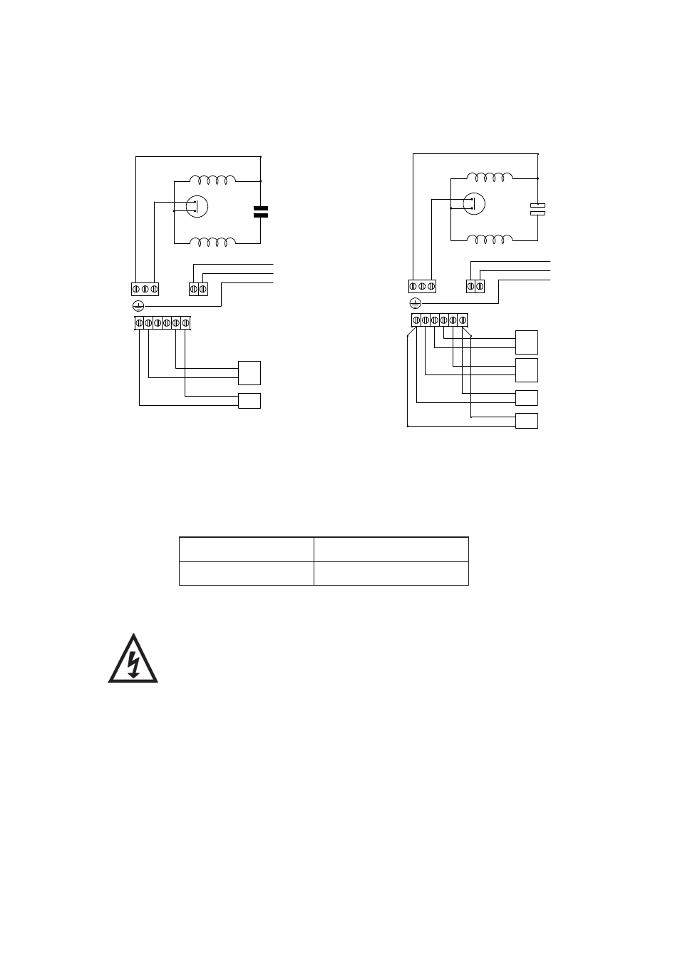
4.21
Wiring Diagrams:
Model
Fuse Size (AMPS)
All other models
5
4.22
Fuses: The following fuse size should be used with the appropriate pump:
MAIN WINDING
THERMOTRIP
CAPACITOR
START WINDING
BLUE
BROWN
BL
ACK
GREEN / YELLOW
BLUE
BROWN
L
E
N 230 VAC/1PH/50Hz
SUPPLY
N A M
N
L
RE
D
S2 S3 S3 S2
S1
S1
FLOWSWITCH
REED (S2)
PRESSURE
SWITCH (S1)
MAIN WINDING
THERMOTRIP
CAPACITOR
START WINDING
FLOWSWITCH
REED (S3)
BLUE
BROWN
BL
ACK
S2 S3 S3 S2
N A M
N
L
RE
D
GREEN / YELLOW
BLUE
BROWN
L
E
N 230 VAC/1PH/50Hz
SUPPLY
S1
S1
FLOWSWITCH
REED (S2)
PRESSURE
SWITCH (S1)
PRESSURE
SWITCH (S1)
Single Models
Fig. 12
Twin Models
Fig. 13