Hot water installations, Step 3 pipework connections (general) – Stuart Turner Monsoon Extra U3.0 bar Single User Manual
Page 6
- 6 -
Cont ...
Before deciding where to locate the unit, check to ensure the static inlet head (Fig. 9)
meets the minimum requirement of 1 metre and does not exceed the maximum
requirement of 8 metres for U1.4 and 10 metres for other models.
The static outlet head (Fig. 9) must also be within the maximum requirement of 8 metres
for U1.4 and 13 metres for other models.
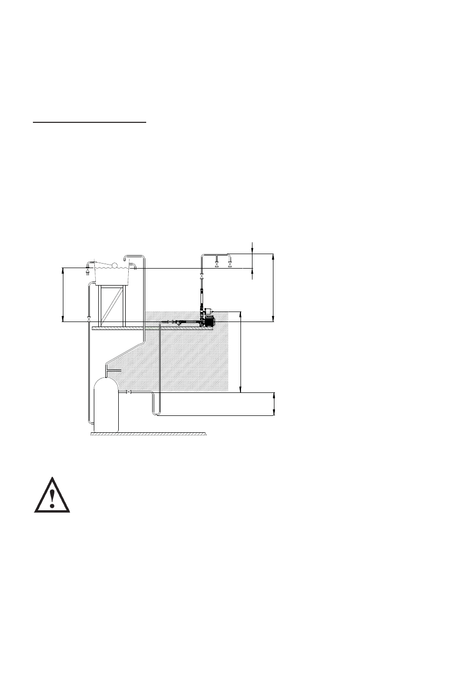
Hot Water Installations
If it is not possible to locate the pump in the preferred area due to site limitations and it is
necessary to position the unit in the loft, or in a position above the secondary tapping that
feeds the pump, then there is an increased risk of air locks. This risk must be eliminated.
The following measure is a suggestion that may overcome the problem:
A “U” bend or downward loop in the supply pipe to the pump of 350 mm depth before
rising to the pump should ensure the cylinder vents its air up the expansion pipe, not up the
pump feed (Fig. 10).
Least Preferred Pump
Location (shaded area).
Pump located above the
hot cylinder can increase
the risk of air locks.
STEP 3 PIPEWORK CONNECTIONS (General)
WARNINGS
Ensure pipework to and from pump is independently supported to
prevent forces being transferred to inlet and outlet branches of pump.
Do not introduce solder flux to pumps or pump parts manufactured
from plastic. All solder joints should be completed and flux residues
removed prior to pump connection.
Do not allow contact with oil or cellulose based paints, paint thinners
or strippers, acid based descalents or aggressive cleaning agents.
Always install isolating valves to both suction and delivery pipework.
Fig. 10
Max. inlet head
10
m (
8
m for U1.4)
Min. inlet head
1
m
Max. outlet head
13
m (
8
m for U1.4)
Negative
head
350
mm
min.
Least preferred area