Yokogawa ISC40 Inductive Conductivity Sensor User Manual
Page 17
IM 12D8J2-E-E
17
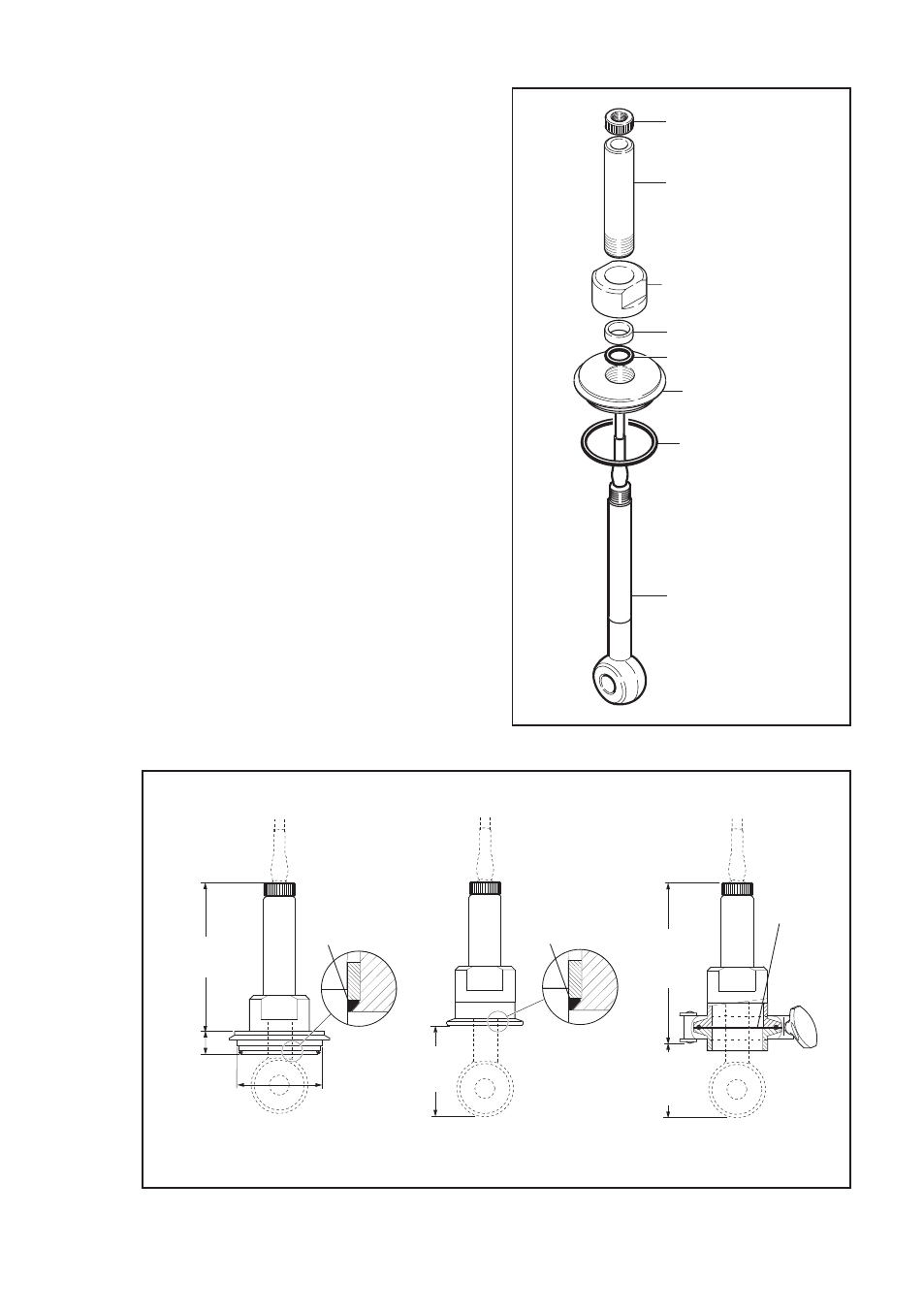
3.1.3 Installation of ISC40G(S)-GS
with flange adapters
The ISC40G(S)-GS sensor is designed for
sanitary applications. For these applications
special process connections are necessary.
Mounting procedure:
• Screw the tube completely in the
stainless steel nut.
• Thread the sensor cable through
the flange adapter parts in the right
sequence.
• Screw the tube hand tight into the flange,
a mechanical stop will be felt.
• Tighten the plastic nut onto the sensor;
screw the plastic nut completely tight.
• Tighten the stainless steel nut for locking
the sensor.
Sensor is installed correctly if the flats on
the sensor are aligned perpendicular on the
process flow.
123 (4.84")
Ø71 (2.80")
19 (0.75")
72 (2.83")
134,3 (5.30")
57,3 (2.25")
O-ring
18.72 x 2.62
O-ring
18.72 x 2.62
O-ring
18.72 x 2.62
2” clamp steal
Tuchenhage
Sanitary 2” Tri-clamp
Tri-clamp complete
/SFT
/STC1
/STC2
Sanitary 2”
Fig 11: Option /SFT, /STC1, /STC2
plastic nut
tube
nut
ring
O-ring 18.7 x 2.6
Tuchenhagen
Flange
Check the O-ring
ø 60 x 3 for correct
mounting.
ISC40G(S)-GS
Fig 10: Installation /SFT