Yokogawa ISC40 Inductive Conductivity Sensor User Manual
Page 15
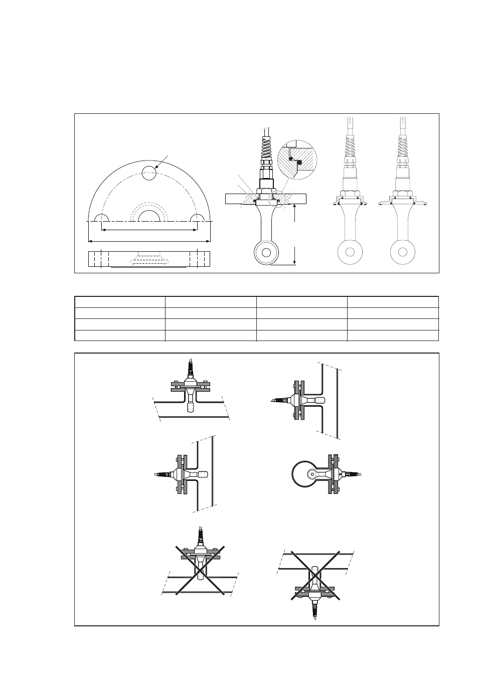
The sensor cable and mounting thread
are pulled through the hole of the flange,
and the sensor is sealed from the process
by tightening the mounting nut. Turning
of the sensor by the torque forces can be
avoided by using a wrench on the flats
on top of the sensor (see fig. 5). Sensor
is installed correctly if the flats are aligned
perpendicular on the process flow.
D2
D1
FLANGE ADAPTER
d
116 (4.56)
O-ring
26.57 x 3.53
40.64 x 5.33
O-ring
26.65 x 2.62
40.87 x 3.53
OK
OK
Not recommended
Not recommended
OK
OK
(air entrapment)
(solid deposits)
Fig 6: Option /SFA, /SFD,
/S2W, /STW
Option
d D1 D2
/SFA
Ø19 (0.75)
121 (4.76)
152 (6.0)
/SFD
Ø18 (0.71)
125 (4.92)
165 (6.5)
/TFD
Ø18 (0.71)
145 (5.71)
185 (7.3)
Fig 7: Installation examples
Flange dimensions in mm (inches)
15
IM 12D8J2-E-E
- EJA130A (4 pages)
- EJA120A (31 pages)
- EJA130A (47 pages)
- EJA120A (40 pages)
- EJA438 (5 pages)
- EJA120A (6 pages)
- EJA115 (85 pages)
- EJA120A (47 pages)
- EJA120A (79 pages)
- EJA130A (2 pages)
- EJA210A (70 pages)
- EJA430A (78 pages)
- EJA130A (4 pages)
- EJX120A (4 pages)
- EJA210E (9 pages)
- EJX115A (55 pages)
- EJA210E (41 pages)
- EJA210E (96 pages)
- EJA210E (52 pages)
- EJA210E (89 pages)
- EJA210E (170 pages)
- FlowNavigator Software (163 pages)
- EJX910A (55 pages)
- EJX910A (175 pages)
- EJX910A (83 pages)
- EJX910A (9 pages)
- EJX910A (103 pages)
- EJA530A (67 pages)
- EJA120A (83 pages)
- EJX530A (52 pages)
- EJA110E (4 pages)
- EJA110E (85 pages)
- EJX120A (85 pages)
- EJA118 (76 pages)
- EJX118A (64 pages)
- EJA438 (72 pages)
- EJA430E (85 pages)
- EJA430E (7 pages)
- EJX430A (6 pages)
- EJX430A (40 pages)
- EJX430A (76 pages)
- EJA430E (96 pages)
- EJA430E (41 pages)
- EJX438A (10 pages)
- ADMAG AXR (194 pages)