Yokogawa EXA ISC202 2-wire Conductivity Transmitter/Analyzer User Manual
Page 95
IM 12D06A03-01E
Appendix 3-3
3/4
QIS 12D06A03-01E
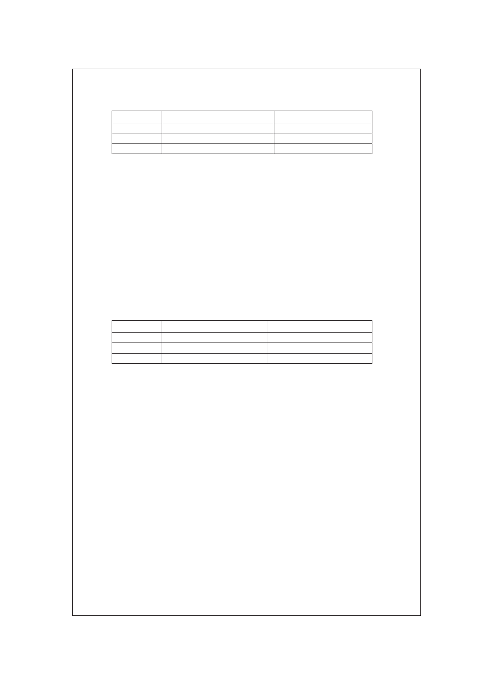
Table 3 SEL.10
Indication
Setpoint of Resistance Box 2
Indication Range
RES. 1
30.00:
0.300±0.002
RES. 3
800.00:
8.00±0.04
RES. 5
30.00k:
300±2
x
Change the number of turns of wire onto the ISC40GJ sensor from ten to one.
x
Press the [ENT] key. The message display shows “ WAIT ” momentarily, followed by
“RES.6.”
x
Set resistance box 2 to the value shown in Table 4 and check the indication. The resistance
indication must be within the range.
x
Press the [ENT] key. The message display shows “ WAIT ” momentarily, followed by
“RES.7.” There is no need to check here, so just press the [ENT] key.
x
The message display shows “ WAIT ” momentarily, followed by “RES.8.”
x
Set resistance box 2 to the value shown in Table 4 and check the indication. The resistance
indication must be within the range.
x
Press the [ENT] key. The message display shows “ WAIT ” momentarily, followed by
“RES.9.”
x
Set resistance box 2 to the value shown in Table 4 and check the indication. The resistance
indication must be within the range.
x
After the test, press the [ENT] key. The message display shows “READY.”
x
Press the [ENT] key to restart the transmitter.
Table 4 SEL1
Indication
Setpoint of Resistance Box 2
Indication Range
RES. 6
300.0:
300±2
RES. 8
8.000k:
8.00±0.10k
RES. 9
80.00k:
80.0±6.3k