Appendix 2, 1. preface, 2. wiring diagrams – Yokogawa EXA ISC202 2-wire Conductivity Transmitter/Analyzer User Manual
Page 73
IM 12D06A03-01E
Appendix 2-1
12. APPENDIX 2
12-1. Preface
This appendix contains these items.
1. Method of wiring and parameter setting the following:.
PH201G*B Dedicated Distributor
BA2O
Junction Terminal Box
WF1OJ Extension
Cable
2. Quick reference for parameter setting
3. Installation factor adjustment.
To ensure that this measurement system can be operated safely and also exhibit its full performance, be
sure to read this appendix before use.
This appendix does not describe SDBT Distributor which is the component unit of the ISC2O2 two-wire
inductive conductivity transmitter system. This unit comes with an instruction manual, so read the instruc-
tion manual IM 1B04T02-01E for details of the unit concerned.
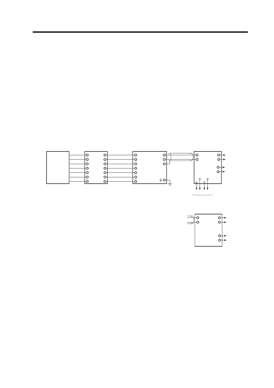
12-2. Wiring diagrams
14
13
Output
(1-5V DC)
A(+)
B(-)
(+)C
(-)D
17
+
-
G
11
12
16
15
Inductive Conductivity
transmitter ISC202G
When PH201G (Style B)
distributor is used
*1
Output
(1-5V DC)
1(+)
2(-)
(+)A
(-)B
SDBT
distributor
*1
Class D (100 ohm or less)
ground
*
2
b
a
d
c
HOLD FAIL
Output
(1-5V DC)
(+)F
(-)H
Relay contact
Non-explosionproof system
Inductive Conductivity
detector ISC40GJ
Output
(1-5V DC)
(+)F
(-)H
*1 Use two-wire cable with OD (Outside Diameter) of 6 to 12 mm
Make sure distributor voltage does not drop below minimum for ISC202G
*2 Ground ISC202G ( Class D ground: 100 ohm or less)
Junction Terminal
Box BA20
Extension Cable
WF10J