4 wiring of the power supply, 4-1 general precautions, 4-2. connection of the power supply – Yokogawa EXA ISC202 2-wire Conductivity Transmitter/Analyzer User Manual
Page 36: 4-3. switching the instrument on, 5. sensor wiring, 4 wiring of the power supply -4, 4-1 general precautions -4, 4-2. connection of the power supply -4, 4-3. switching the instrument on -4, 5. sensor wiring -4
IM 12D06A03-01E
3-4 Installation and wiring
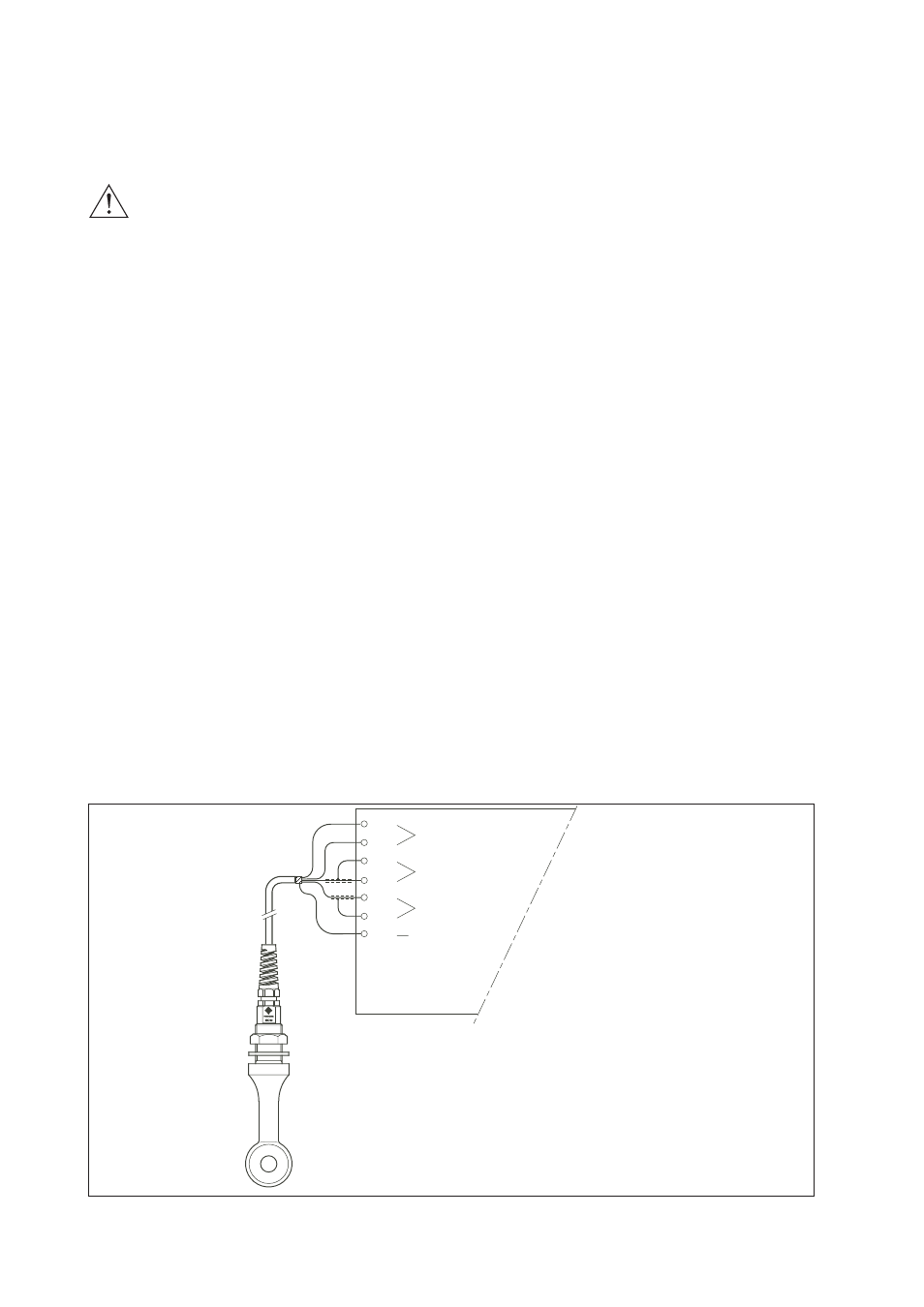
Figure 3-7. Sensor wiring diagrams
3-4 Wiring of the power supply
3-4-1 General precautions
First make sure that the DC-power supply is according the specifications given.
DO NOT USE ALTERNATING CURRENT OR MAINS POWER SUPPLY! !
The cable leading to the distributor (power supply) or safety barrier transports power to an output signal
from the transmitter. Use a two conductor shielded cable with a size of at least 1.25 mm
2
and an outside
diameter of 6 to 12 mm. The cable gland supplied with the instrument accepts these diameters. The
maximum length of the cable is 2000 mtr, or 1500 mtr when using the communications. This ensures the
minimum operating voltage for the instrument.
Grounding:
• If the transmitter is mounted on a grounded surface (e.g. a metal frame fixed in the soil) the shield of
the 2-wire cable may NOT be connected to ground at the distributor.
• If the transmitter is mounted on a non-conducting surface (e.g. a brick wall) it is recommended to
ground the shield of the 2-wire cable at the distributor end.
3-4-2. Connection of the power supply
The terminal strip is accessed as was described in 3-2-1. Use the left-hand gland to insert the supply/
output cable to the transmitter. Connect the supply to the terminals marked +, - and G as is indicated in
figures 3-8.
3-4-3. Switching the instrument on
After all connections are made and checked, the power can be switched on from the distributor. Observe
the correct activation of the instrument at the display. If for any reason the display does not indicate a
value, consult the trouble shooting section.
3-5. Sensor wiring
Refer to figure 3-7, which includes drawings that outline sensor wiring.
To connect the sensors, simply match the terminal numbers in the instrument with the identification num-
bers on the cable ends.
WARNING
Thermistor (Temperature sensor)
ground (shield)
Secondary Coil
Primary Coil
11
12
17
13
15
16
14