4 dimensions, 4 dimensions -7, Model eja115 [style: s3 – Yokogawa EJA115 User Manual
Page 71
IM 01C22K01-01E
10-7
10. GENERAL SPECIFICATIONS
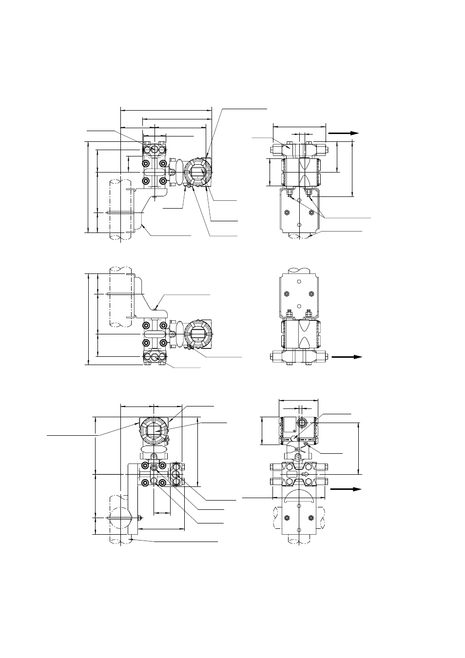
10.4
Dimensions
᭹ Model EJA115 [Style: S3]
Unit: mm(approx. inch)
External indicator
conduit connection
(Optional)
Ground
terminal
Mounting bracket
(L-type, Optional)
Conduit
connection
Internal
indicator
(Optional)
Zero
adjustment
63
(2.48)
102
(4.02)
53
( 2.09)
242(9.53)
259(10.20)
197 (7.76)
97
(3.82)
146 (5.75)
46
(1.81)
63 (2.48)
Process
connections
2-inch pipe
(O.D. 60.5mm)
Vent/Drain plugs
Terminal
side
149 (5.87)
87
(3.43)
156
(6.14)
ø78
(3.07)
9 *
1
(0.35)
Flow
direction
(Note)
Manifold
63
(2.48)
102
(4.02)
53
( 2.09)
242(9.53)
Process
connections
Vent/Drain plugs
Flow
direction
(Note)
Vertical Impulse Piping Type, Manifold downside(INSTALLATION CODE '7')
Horizontal Impulse Piping Type(INSTALLATION CODE '9')
Vertical Impulse Piping Type, Manifold upside(INSTALLATION CODE '6')
94
(3.70)
80
(3.15)
197
(7.76)
46
(1.81)
134 (5.28)
162
(6.38)
124
(4.88)
47
(1.85)
External indicator
conduit connection
(Optional)
Conduit
connection
2-inch pipe (O.D. 60.5mm)
Internal
indicator
(Optional)
Process
connections
Zero
adjustment
Ground
terminal
Vent plugs
Terminal
side
Drain plugs
149
(5.87)
ø78
(3.07)
146
(5.75)
110 (4.33)
9 *
1
(0.35)
Flow
direction
(Note)
F1002.EPS
Shrouding bolt
*2
Note:
When INSTALLATION CODE ‘2’, ‘3’ or ‘8’ is selected, flow direction arrow mark on above figure
are reversed.
(i. e. Arrow head faces toward left.)
*1:
15 mm (0.59 inch) for right side high pressure. (INSTALLATION CODE ‘2’, ‘3’ or ‘8’)
*2:
Applicable only for ATEX, IECEx, and TIIS Flameproof type.